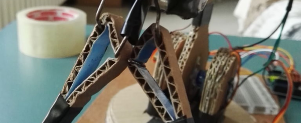
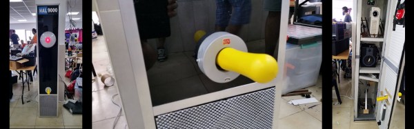
 Check out the great workmanship that went into [TonyRobot]’s coffee vending version of ROBOT CAFE at Tokyo Maker Faire 2016. We’d really like to see this in action, so if anyone has more success than we did at tracking down more info (especially if it’s video) let us know in the comments below. We spot laser-cut wood making up the clever scoop design (and the numerous gears within it) but simply must know more.
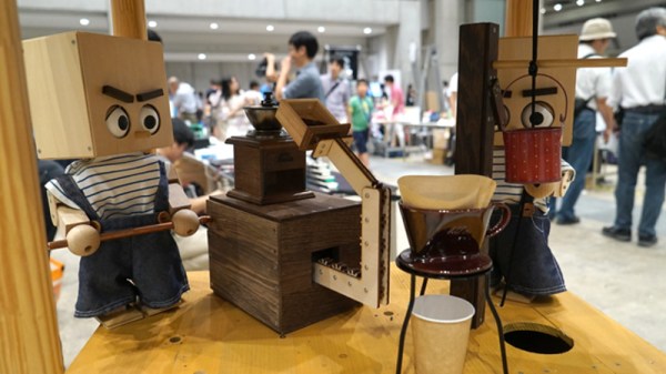
Technically this is less “robot” and more “automata“. The cart charmingly fuses vending machine practicality with a visual display… and a great one at that. The aesthetic of the Robot Cafe leaps over the uncanny valley and fully embraces lovable robot faces.
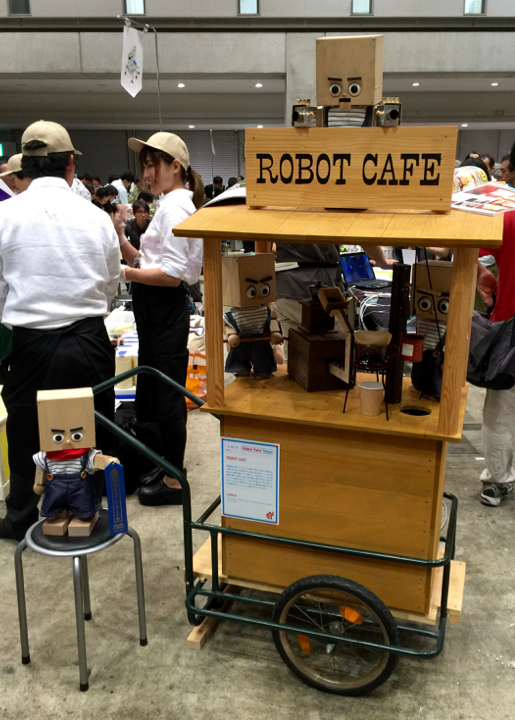
Coffee is ground by a manual-style grinder into a scoop, which is then dumped into a pour-over filter. The hot water is then raised from below to pour over the grounds. These characters can be reconfigured based on the needs of the venue. The creator page linked above has three pictures of the same cart and same robo-baristas, but they are fishing for sodas instead. The glass bottles are lifted through the hole you can see on the right of the cart’s counter, using a fishing line with a magnet to grip the metal bottle cap.
We were delighted when robot vending machines started to appear — the kind with a big glass window and a gantry that grabs your corn-syrupy beverage. But take inspiration from this. True vending nirvana is as much theater as it is utility.
[via Gizmodo Japan]


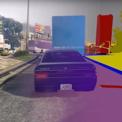 The hard problem with this approach is getting a large enough sample for the machine learning to be viable. The idea is this: the virtual world provides a far more efficient solution to supplying enough data to these programs compared to the time-consuming task of annotating object data from real-world images. In addition to scaling up the amount of data, researchers can manipulate weather, traffic, pedestrians and more to create complex conditions with which to train AI.