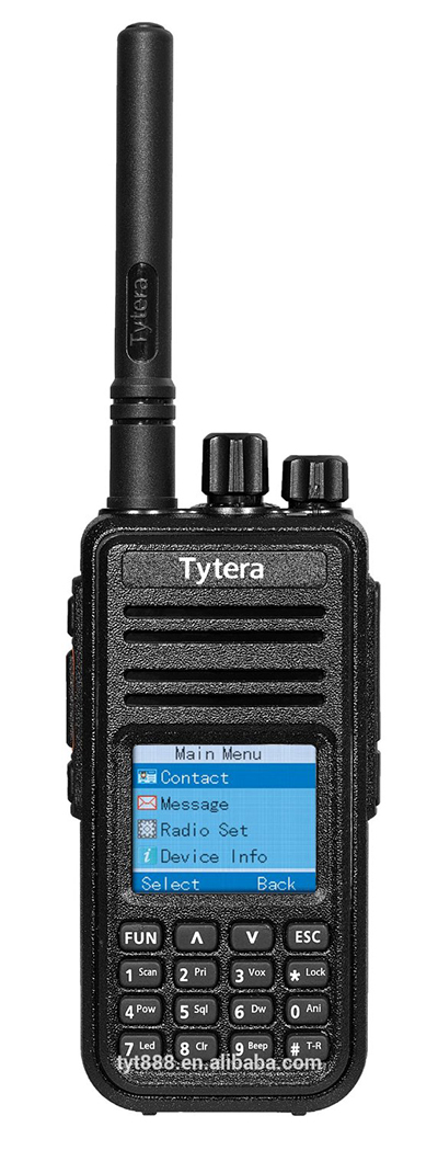
Every once in a great while, a piece of radio gear catches the attention of a prolific hardware guru and is reverse engineered. A few years ago, it was the RTL-SDR, and since then, software defined radios became the next big thing. Last weekend at Shmoocon, [Travis Goodspeed] presented his reverse engineering of the Tytera MD380 digital handheld radio. The hack has since been published in PoC||GTFO 0x10 (56MB PDF, mirrored) with all the gory details that turn a $140 radio into the first hardware scanner for digital mobile radio.
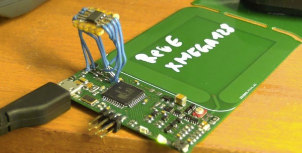
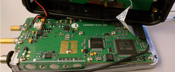
The Tytera MD380 is a fairly basic radio with two main chips: an STM32F405 with a megabyte of Flash and 192k of RAM, and an HR C5000 baseband. The STM32 has both JTAG and a ROM bootloader, but both of these are protected by the Readout Device Protection (RDP). Getting around the RDP is the very definition of a jailbreak, and thanks to a few forgetful or lazy Chinese engineers, it is most certainly possible.
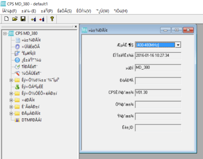
The STM32 in the radio implements a USB Device Firmware Upgrade (DFU), probably because of some example code from ST. Dumping the memory from the standard DFU protocol just repeated the same binary string, but with a little bit of coaxing and investigating the terrible Windows-only official client application, [Travis] was able to find non-standard DFU commands, write a custom DFU client, and read and write the ‘codeplug’, an SPI Flash chip that stores radio settings, frequencies, and talk groups.
Further efforts to dump all the firmware on the radio were a success, and with that began the actual reverse engineering of the radio. It runs an ARM port of MicroC/OS-II, a real-time embedded operating system. This OS is very well documented, with slightly more effort new functions and patches can be written.
In Digital Mobile Radio, audio is sent through either a public talk group or a private contact. The radio is usually set to only one talk group, and so it’s not really possible to listen in on other talk groups without changing settings. A patch for promiscuous mode – a mode that puts all talk groups through the speaker – is just setting one JNE in the firmware to a NOP.
With the help of [DD4CR] and [W7PCH], the entire radio has been reverse engineered with rewritten firmware that works with the official tools, the first attempts of scratch-built firmware built around FreeRTOS, and the beginnings of a very active development community for a $140 radio. [Travis] is looking for people who can add support for P25, D-Star, System Fusion, a proper scanner, or the ability to send and receive DMR frames over USB. All these things are possible, making this one of the most exciting radio hacks in recent memory.
Before [Travis] presented this hack at the Shmoocon fire talks, intuition guided me to look up this radio on Amazon. It was $140 with Prime, and the top vendor had 18 in stock. Immediately after the talk – 20 minutes later – the same vendor had 14 in stock. [Travis] sold four radios to members of the audience, and there weren’t that many people in attendance. Two hours later, the same vendor had four in stock. If you’re looking for the best hardware hack of the con, this is the one.


 running a calculus function on an Arduino presents a seemingly impossible scenario. In this article, we’re going to explore the idea of using derivative like techniques with a microcontroller. Let us be reminded that the derivative provides an instantaneous rate of change. Getting an instantaneous rate of change when the function is known is easy. However, when you’re working with a microcontroller and varying analog data without a known function, it’s not so easy. Our goal will be to get an average rate of change of the data. And since a microcontroller is many orders of magnitude faster than the rate of change of the incoming data, we can calculate the average rate of change over very small time intervals. Our work will be based on the fact that the average rate of change and instantaneous rate of change are the same over short time intervals.