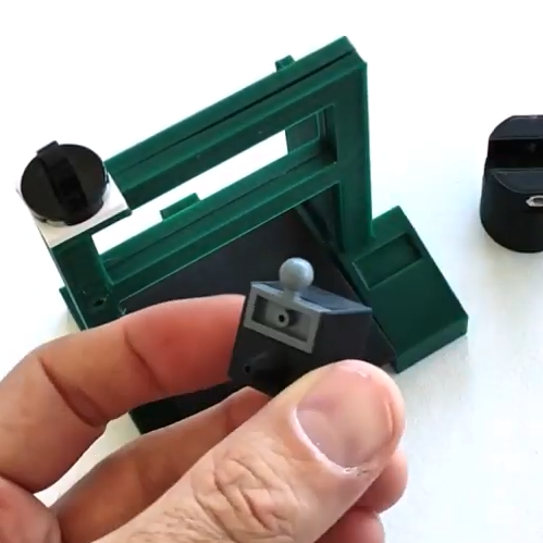
A few Lego pieces provide key functionality, like an articulated dispenser head.
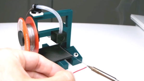
Most of us have bent a length of solder into a more convenient shape and angle when soldering, and just sort of pushed the soldering iron and work piece into the hanging solder instead of breaking out a third hand. Well, [yukseltemiz] seems to have decided that a solder dispenser and a miniature 3D printer model can have a lot in common, and created a 1/5 scale Ender 3 printer model that acts as a solder stand and dispenser. The solder spool hangs where the filament roll would go, and the solder itself is dispensed through the “print head”.
It’s cute, and we do like the way that [yukseltemiz] incorporated a few Lego pieces into the build. A swivel and eyelet guides the solder off the roll and a small Lego ball and socket gives the dispenser its articulation, an important feature for bending solder to a more convenient angle for working. It makes us think that using Lego pieces right alongside more traditional hardware like M3 nuts and bolts might be an under-explored technique. You can see the unit in action in the brief assembly video, embedded below.
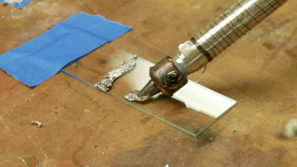
Ultrasonic soldering is a little-known technology that allows soldering together a variety of metals and ceramics that would not normally be possible. It requires a special ultrasonic soldering iron and solder that is not cheap or easy to get hold of, so [Ben Krasnow] of [Applied Science] made his own.
Ultrasonic soldering irons heat up like standard irons, but also require an ultrasonic transducer to create bonds to certain surfaces. [Ben] built one by silver soldering a piece of stainless steel rod (as a heat break) between the element of a standard iron and a transducer from an ultrasonic cleaner. He made his special active solder by melting all the ingredients in his vacuum induction furnace. It is similar to lead-free solder, but also contains titanium and small amounts of cerium and gallium. In the video below [Ben] goes into the working details of the technology and does some practical experimentation with various materials.
Ultrasonic soldering is used mainly for electrically bonding metals where clamping is not possible or convenient. The results are also not as neat and clean as with standard solder. We covered another DIY ultrasonic soldering iron before, but it doesn’t look like that one ever did any soldering.
Ultrasonic energy has several interesting mechanical applications that we’ve covered in the past, including ultrasonic cutting and ultrasonic welding.
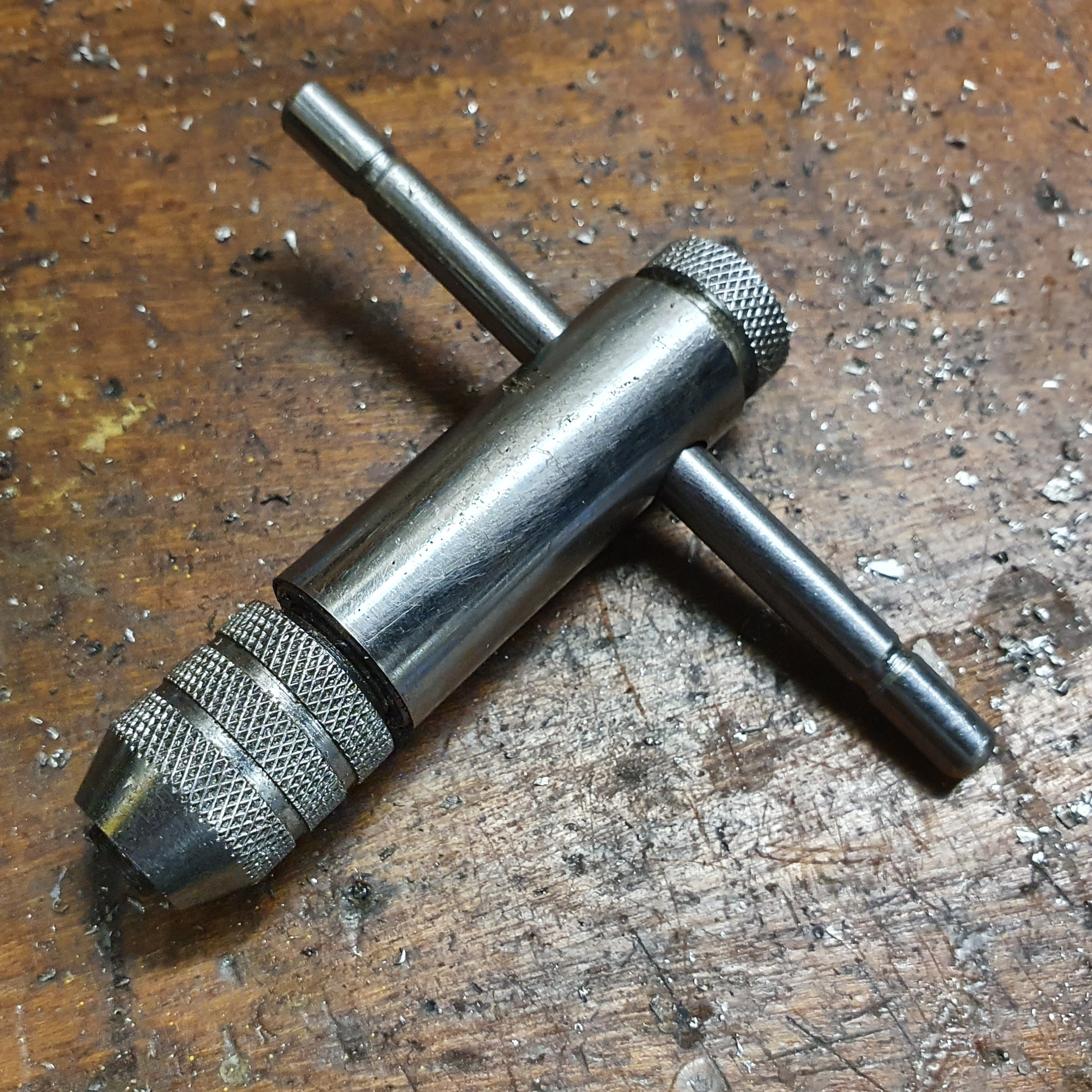
Need to cut threads into a hole? A tool called a tap is what you need, and a hand-operated one like the one shown here to the side is both economical and effective. A tap’s cutting bit works by going into a pre-drilled hole, and it’s important to keep the tool straight as it does so. It’s one thing to tap a few holes with steady hands and a finely calibrated eyeball, but when a large number of holes need to be tapped it can be worth getting a little help.
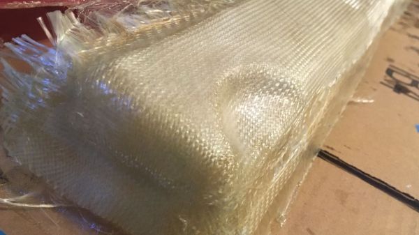
Hide glue has been around for thousands of years, and some of it is holding wood pieces three thousand years after application. It is made from animal protein, so vegetarians may want to stick to the petroleum-based adhesives. [Surjan Singh] wanted to see if its longevity made it a contender with modern epoxy by casting a couple of fiberglass car parts with the competing glues. In short, it doesn’t hold up in this situation, but it is not without merit.
Musical instrument makers and antique restorers still buy and use hide glue, but you would never expose it to heat or moisture. To its credit, hide glue doesn’t require a ventilator. All you need is boiling water and a popsicle stick, and you are in business. [Surjan] writes his findings like a narrative rather than steps, so his adventures are a delight to read. He found that a car part made with fiberglass and epoxy will withstand the weather better than the alternative because heat and humidity will soften hide glue. His Saab 96 isn’t the right application, but since it is nearly as strong as epoxy once set, you could make other fabric shapes, like a flannel nightstand or a lace coffee table, and you could shape them in the living room without toxifying yourself
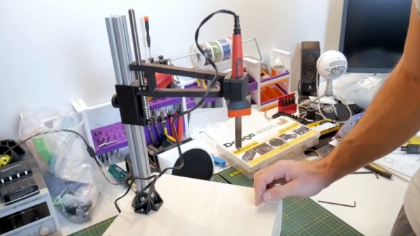
If you’re building mechanical assemblies with 3D printed parts, you’ll quickly realize that driving machine screws into thermoplastic isn’t exactly an ideal solution. It can work in a pinch, but you can easily strip the threads if you crank down too hard. The plastic holes can also get worn down from repeated use, which is a problem if you’re working on something that needs to be taken apart and reassembled frequently. In those situations, using brass heat set inserts gives the fasteners something stronger to bite into.
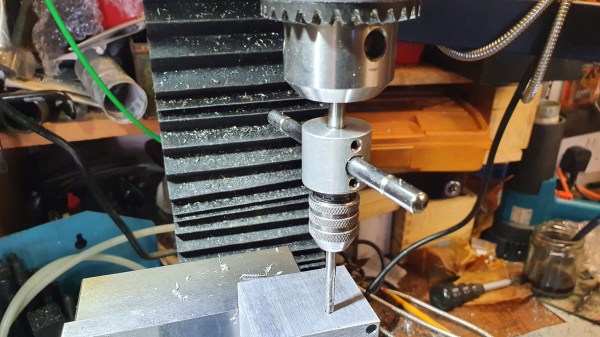
You can install these inserts by hand, but if you plan on doing a lot of them, a dedicated press station like the one [Chris Chimienti] recently put together will save you a lot of aggravation in the long run. In the video after the break he walks viewers through the design and use of the device, which itself relies on a number of 3D printed parts using the very same inserts it’s designed to install.
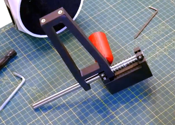
The spring-loaded arm can slide up and down the extrusion to adjust for height.
To build this tool you’ll need a piece of aluminum extrusion, some smooth rod, a couple springs, and an assortment of fasteners. Nothing that wouldn’t likely be in the parts bin of anyone who’s been tinkering with 3D printers for awhile, though even if you had to buy everything, the Bill of Materials will hardly break the bank. For the base you can use a piece of scrap wood, though [Chris] has opted to make it a storage compartment where he can store the inserts themselves. We really like this approach, but obviously you’ll need to have access to woodworking tools in that case.
Clearly shopping on the top shelf, [Chris] purchased a kit that actually came with a Weller soldering iron and the appropriate tips for the various sized inserts. If you’re like us and just buy the inserts that come in a plastic baggie, you may need to adapt the arm to fit your iron of choice. That said, the idea of having a dedicated iron that you can leave mounted in the press makes a lot of sense to us if you can swing it.
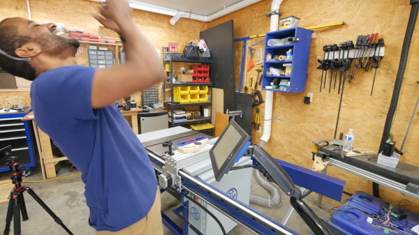
Typically, someone’s first venture into coding doesn’t get a lot of attention. Then again, most people don’t program a CNC table saw right out of the gate. [Jeremy Fielding] wasn’t enticed with “Blink” or “Hello, world,” and took the path less traveled. He tackled I/O, UX, and motion in a single project, which we would equate to climbing K2 as a way to get into hiking. The Python code was over 500 lines, so we feel comfortable calling him an over-achiever.
The project started after he replaced the fence on his saw and wondered if he could automate it, and that was his jumping-on point, but he didn’t stop there. He automated the blade height and angle with stepper motors, so the only feedback is limit switches to keep it from running into itself. The brains are a Raspberry Pi that uses the GPIO for everything. There is a manual mode so he can use the hand cranks to make adjustments like an ordinary saw, but he loses tracking there. His engineering background shines through in his spartan touchscreen application and robust 3D model. The built-in calculator is a nice touch, and pulling the calculations directly to a motion axis field is clever.
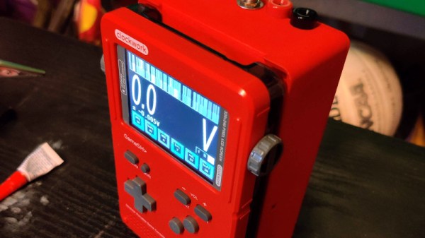
There are many different single board computers that are general purpose, but there’s another breed targeted at specific applications. One such is the Clockworkpi, a handheld Game Boy-style games console, which may be aimed at gamers but has just as much ability to do all the usual SBC stuff. It’s something [UncannyFlanigan] has demonstrated, by turning the Clockworkpi into a multimeter. And it’s not just a simple digital multimeter either, it’s one that sports graphing as well as instantaneous readings.
At its heart is an Arduino board that supplies the analogue to digital conversion, with opto-couplers for isolation between the two boards. A simple three-way switch selects voltage, current, and resistance ranges, and the ClockworkPi interface is written in Python. We can see that this could easily be extended using the power of the Arduino to deliver more functionality, for which all the code is handily available in a GitHub repository. It’s not a perfect multimeter yet because it lacks adequate input protection, but it shows a lot of promise.