Buying tools is all well and good, but it doesn’t suit the ethos of Youtube channel [Workshop From Scratch]. Building what you need is much more the go, and that’s demonstrated ably with this home-built electric workshop crane.
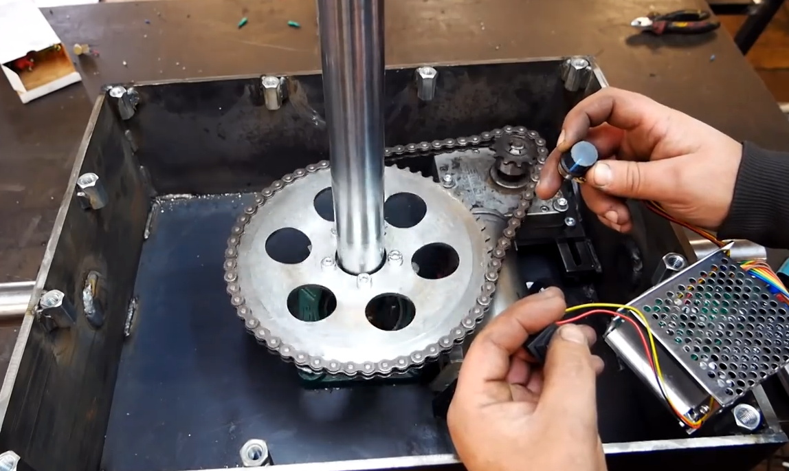
The crane is put together in a straightforward manner using basic steelworking techniques. Plates and bars are machined with a drill press, bandsaw and grinder, though we could imagine you could use hand tools if you were so inclined. An ATV winch is pressed into service to do the heavy lifting, powered by a set of 12V lead acid batteries placed in the base. This design choice does double duty as both a mobile power supply for the crane, and acts as a counterweight in the base.
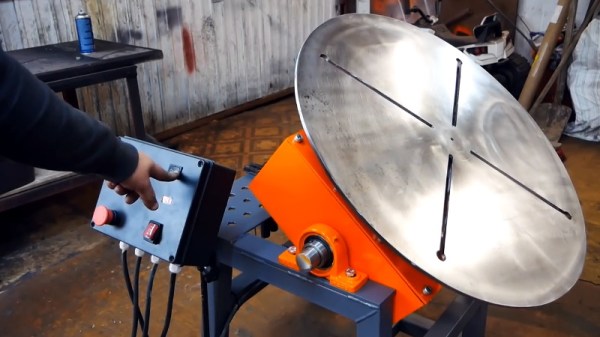
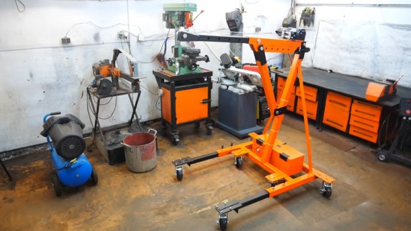
The final result looks sharp in its orange paint finish, and does a good job of moving heavy equipment around the workshop. The legs are reconfigurable, so that even very heavy loads can be lifted with appropriate counterweight placed on the back. It’s a significant upgrade on the earlier version we featured last year, which was hydraulic in operation. Video after the break.