Putting The Magic Smoke Back Into A Dodgy Spectrum Analyzer

The trouble with fixing electronics is that most devices are just black boxes — literally. Tear it down, look inside, but it usually doesn’t matter — all you see are black epoxy blobs, taunting you with the fact that one or more of them are dead with no external indication of the culprit.

Sometimes, though, you get lucky, as [FeedbackLoop] did with this Rigol spectrum analyzer fix. The instrument powered up and sort of worked, but the noise floor was unacceptably high. Even before opening it up, there was clearly a problem; in general, spectrum analyzers shouldn’t rattle. Upon teardown, it was clear that someone had been inside before and got reassembly wrong, with a loose fastener and some obviously shorted components to show for it. But while the scorched remains of components made a great place to start diagnosis, it doesn’t mean the fix was going to be easy.

Figuring out the values of the nuked components required a little detective work. The blast zone seemed to once hold a couple of resistors, a capacitor, a set of PIN diodes, and a couple of tiny inductors. Also nearby were a pair of chips, sadly with the markings lasered off. With some online snooping and a little bit of common sense, [FeedbackLoop] was able to come up with plausible values for most of these — even the chips, which turned out to be HMC221 RF switches.

Cleaning up the board was a bit of a chore — the shorted components left quite a crater in the board, which was filled with CA glue, and a bunch of missing pads. This called for some SMD soldering heroics, which sadly didn’t fix the noise problem. Replacing the two RF switches and the PIN diodes seemed to fix the problem, albeit at the cost of some loss. Sometimes, good enough is good enough.

This isn’t the first time [FeedbackLoop] has gotten lucky with choice test equipment in need of repairs — this memory module transplant on a scopemeter comes to mind.

Continue reading “Putting The Magic Smoke Back Into A Dodgy Spectrum Analyzer”

Bringing Da Vinci’s Saw Mill To Life

DaVinci’s notebook — the real one, not the band — was full of wonderous inventions, though many were not actually built and probably weren’t even practical with the materials available at the time (or even now). [How To Make Everything] took one of the Master’s drawings from 1478 of a sawmill and tried to replicate it. How did he do? You can see for yourself in the video below.

There are five different pieces involved. A support structure holds a water wheel and a saw. There’s a crank mechanism to drive the saw and a sled to move the wood through the machine. It sounds simple enough, although we were impressed and amused that he made his own nails to be authentic. No Home Depot back in the 1470s, after all.

Watching him produce, for example, castle joints, makes us think, “Hey, we could do that!” But, of course, we probably can’t, at least not by hand. We must admit we are pretty dependent on CNC tools and 3D printing, but we admire the woodwork, nevertheless. There’s some pretty cool metal working, too.

We thought the waterwheel would be the easy part, but it turned out to be a bit of a problem. Things worked, but it was slower than you would think. We’ve seen sawmills put together before. Da Vinci worked for money, and there was always money in weapons so he did design a lot of them, too.

Continue reading “Bringing Da Vinci’s Saw Mill To Life”

Agreeing By Disagreeing

While we were working on the podcast this week, Al Williams and I got into a debate about the utility of logic analyzers. (It’s Hackaday, after all.) He said they’re almost useless these days, and I maintained that they’re more useful than ever. When we got down to it, however, we were actually completely in agreement – it turns out that when we said “logic analyzer” we each had different machines, and use cases, in mind.

Al has a serious engineering background and a long career in his pocket. When he says “logic analyzer”, he’s thinking of a beast with a million probes that you could hook up to each and every data and address line in what would now be called a “retrocomputer”, giving you this god-like perspective on the entire system state. (Sounds yummy!) But now that modern CPUs have 64-bits, everything’s high-speed serial, and they’re all deeply integrated on the same chip anyway, such a monster machine is nearly useless.

Meanwhile, I’m a self-taught hacker type. When I say “logic analyzer”, I’m thinking maybe 8 or 16 signals, and I’m thinking of debugging the communications between a microcontroller, an IMU, or maybe a QSPI flash chip. Heck, sometimes I’ll even break out a couple pins on the micro for state. And with the proliferation of easy and cheap modules, plus the need to debug and reverse commodity electronics, these logic analyzers have never been more useful.

So in the end, it was a simple misunderstanding – a result of our different backgrounds. His logic analyzers were extinct or out of my price range, and totally off my radar. And he thinks of my logic analyzer as a “simple serial analyzer”. (Ouch! But since when are 8 signals “serial”?)

And in the end, we both absolutely agreed on the fact that great open-source software has made the modern logic analyzers as useful as they are, and the lack thereof is also partially responsible for the demise of the old beasts. Well, that and he needs a lab cart then to carry around what I can slip in my pocket today. Take that!

Wien Bridge Oscillator Drives Distortion Into The Floor

It’s not often that a single photo can tell you pretty much everything you need to know about a project, but the spectrum analyzer screenshot nearby is the perfect summary of this over-the-top low-distortion audio oscillator build. But that doesn’t mean there’s not a ton of interesting stuff going on with this one, so buckle up.

One spike at the fundamental and not much more.

The project is by [Basin Street Design], who doesn’t really offer much by way of inspiration for this undertaking, nor a discussion on what this will be used for. But the design goals are pretty clear: build an oscillator with as little distortion as possible across the audio frequency range.

The basic circuit is the well-known Wien bridge oscillator where the R-C pairs are switched in and out of the feedback loop to achieve frequency range control. This was accomplished with rotary switches rebuilt from their original configuration in a Heathkit IG-18 sine/square wave generator, a defunct instrument that was gutted and used as an enclosure for this build. There are a lot of other treats here, too, like the automatic gain control (AGC) that uses a homebrew voltage-controlled resistor made from an incandescent lamp and a cadmium sulfide photoresistor glued inside a piece of brake line, and an output attenuator made from discrete resistors that drops the output in 10 dB steps while maintaining an overall 75-Ohm impedance.

But at the end of the day, it all comes down to that single spike on the spectrum analyzer, with no apparent harmonics. To make sure there wasn’t something hiding down in the noise, [Basin Street] added a notch filter to lower the fundamental by 60 dB, allowing the spectrum analyzer sensitivity to be cranked way up. Harmonics were visible, but so far down into the noise — as low as -115 dBc — that it’s hardly worth mentioning.

There’s a lot more detail in this one, so dive in and enjoy. If you want another take on Wien bridge circuits, check out this recent LM386-based oscillator. Just don’t expect such low distortion with that one.

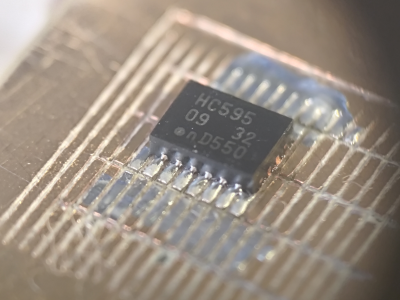
Finally, A Machine To Organize Resistors!

Perhaps it’s a side-effect of getting older, but it seems like reading the color bands on blue metal-film resistors is harder than it was on the old brown carbon ones. So often the multimeter has to come out to check, but it’s annoying. Thus we rather like [Mike]’s Resistorganizer, which automates the process of keeping track of the components.

At its heart is a fairly simple concept, with the microcontroller reading the value of a resistor by measuring the voltage from a potential divider. The Resistorganizer extends this using an array of analogue multiplexer chips, and is designed to plug into one side of a breadboard with the idea being that each line can have a resistor connected to earth through it. Of course it’s not quite as simple as that, because to maintain a readable range a set of resistors must be switched in and out to form the other half of the divider for different ranges. Thus another multiplexer chip performs that task.

Finally a set of digital multiplexers handles an LED to see which of the many resistors is currently selected through a pair of buttons, and a dot-matrix LCD display delivers the value. We want one already!

Fiery Torch Build Is Remarkably Stylish

Hollywood movies, RPGs, and Dungeons and Dragons campaigns are all full of flaming torches. They’re a typical source of light in scenarios where electrical solutions simply aren’t available. [Wesley Treat] decided to build a rather attractive ceremonial torch of his own design, showing off his impressive crafting skills in the process.

The torch ignited a pretty rad sculpture.

The build starts with a foam simulacra that helps [Wesley] rough out the general shape of the torch. It’s a little shorter and stubbier than an Olympic torch might be, for reference. The main body of the torch is then hewn out of stout wooden blocks with the aid of a bandsaw with a nifty angle-adjustable cutting bed. A torch was then used to heat and bend steel strip  to make an attractive and heat-resistant flame shroud to sit on top. A wad of fuel-soaked material installed inside the shroud serves as the actual flaming compoment.

[Wesley] built the torch for the Maker Burn at Maker Camp in upstate New York. It did a plenty good job of helping burn down the giant scrap wood jackalope  sculpture built for the event. We do love the fire and the flames around these parts. Video after the break.

Continue reading “Fiery Torch Build Is Remarkably Stylish”

Hackaday Prize 2023: 10 KW Electronic Load

[tinfever] needed a high-power benchtop electronic load for an upcoming project, and by their own admission decided foolishly to build their own. And we’re glad they did. The thing is, whilst this isn’t exactly a super-cheap project to build, buying a commercial offering with a capability of 10 kW and up to 30 kW pulsed, is going to cost an absolute fortune.

A selection of small resistors

Built inside a cubic frame using what appears to be standard 2020 aluminum rails and fixturing, the modular construction is nice and clean, with plenty of space around the load boards to allow the cooling air to circulate.

The operating principle is very simple; custom PCBs act in parallel to provide any load needed, by switching in the on-board load resistor. Each load board handles all the details of switching and dumping the power due to the inductance in the system wiring and the wire-wound resistors themselves.

Whilst we know that wire-wound resistors are reverse-wound to minimize inductance, there will still be some, and each load board will contribute a little more when the whole system is scaled up. Also, each load PCB handles its own temperature sensing, and current measurement passing these data off to the control PCB. A front-end connector PCB provides a variety of connection options to interface to the DUT (Device Under Test.) The system controller is based around an STM32 processor which deals with quite a lot more than you might think is needed on a first look.

The sense currents from each load need to be sensed, scaled, and summed to keep the overall load accuracy within the 1% spec. Also, it is on duty for PWM control of the cooling fans, handling the user interface, and any other remote connectivity. There are a lot of details on the project page, as we’re only skimming the surface here. If you’re interested in building an active load, this is a project you really should be digging into.

We shall watch with interest for when [tinfever] scales up this eight-slot prototype to the full specification of 52 stages! When working with power applications, there comes a point when you really need an electronic load, and to that end, here’s one with a very specific use case to get you started.

There is also the option of buying something cheap from the usual sources and hacking on some custom firmware to adapt it a little to your needs.