Troubleshooting a circuit is easy, right? All you need is a couple of hands to hold the probes, another hand to twiddle the knobs, a pair of eyes to look at the schematic, another pair to look at the circuit board, and, for fancy work, X-ray vision to see through the board so you know what pads to probe. It’s child’s play!
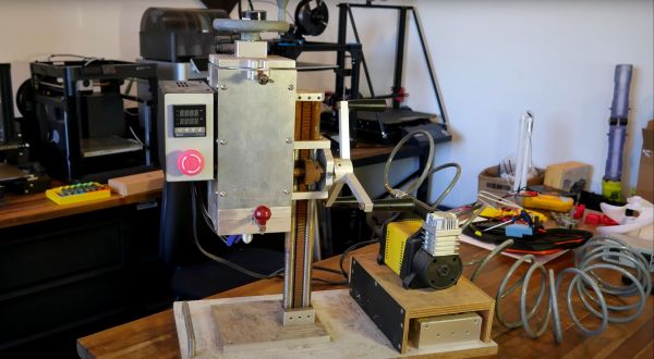
In the real world, most of us don’t have all the extra parts needed to do the job right, which is where something like CircuitScout would come in mighty handy. [Fangzheng Liu] and [Thomas Juldo]’s design is a little like a small pick-and-place machine, except that instead of placing components, the dual gantries place probes on whatever test points you need to look at. The stepper-controlled gantries move independently over a fixture to hold the PCB in a known position so that the servo-controlled Z-axes can drive the probes down to the right place on the board.
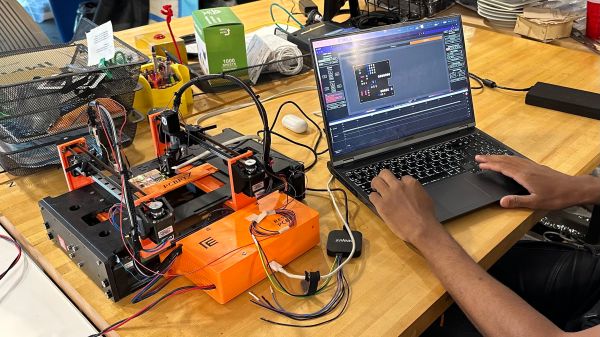
As cool as the hardware is, the real treat is the software. A web-based GUI parses the PCB’s KiCAD files, allowing you to pick a test point on the schematic and have the machine move a probe to the right spot on the board. The video below shows CircuitScout moving probes from a Saleae logic analyzer around, which lets you both control the test setup and see the results without ever looking away from the screen.
CircuitScout seems like a brilliant idea that has a lot of potential both for ad hoc troubleshooting and for more formal production testing. It’s just exactly what we’re looking for in an entry for the Gearing Up round of the 2023 Hackaday Prize.
Continue reading “Hackaday Prize 2023: Circuit Scout Lends A Hand (Or Two) For Troubleshooting”