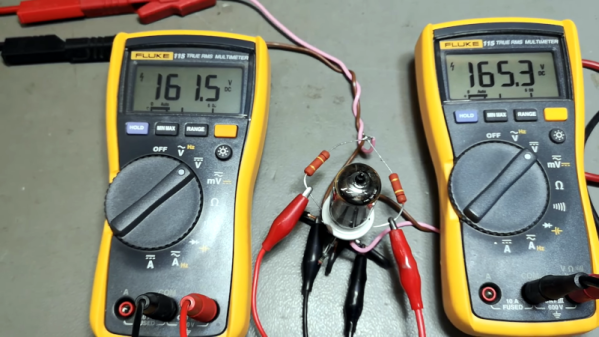
Measuring a voltage is pretty easy: just place your multimeter’s probes across the relevant pins and read the value. Probing currents is a bit trickier, since you need to open up the circuit and place your probes in series. Checking a circuit’s power consumption is the hardest, since you need to measure both voltage and current as well as multiply them at each moment in time. Fed up with having to hook up two multimeters and running a bunch of synchronized measurements, [Per-Simon Saal] built himself an automatic digital power meter.
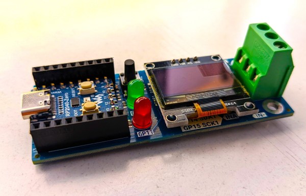
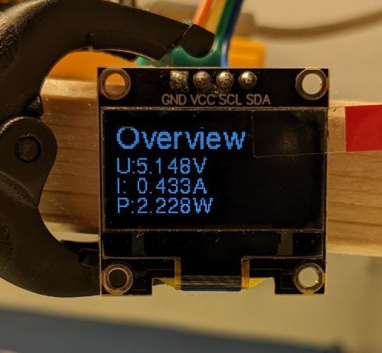
The heart of this instrument is an INA219 chip, which can measure and digitize voltage and current simultaneously. It outputs the results through an I2C bus, which [Per-Simon] hooked up to a miniaturized version of the Raspberry Pi Pico called an RP2040-Zero. A screw terminal block is provided to connect the system to the device under test, while a 0.96″ OLED display shows the measured voltage, current and power.
 The maximum voltage that can be measured is 26 V, while the current range is determined by the shunt resistor mounted on the board. The default shunt is 0.1 Ω, resulting in a 3.2 A maximum current range, but you can get pretty much any range you want by simply mounting a different resistor and changing the software configuration. In addition to displaying the instantaneous values, the power meter can also keep a log of its measurements – very useful for debugging circuits that use more energy than expected or for measuring things like the capacity of a battery.
There are lots of ways to measure electric power, but they all boil down to multiplying current and voltage in some way. The multiplication was done magnetically in the old days, but modern meters like [Per-Simon]’s of course use digital systems. Some can even plug directly into a USB port. If you want to measure mains power, transformers are an essential component for safety reasons.