[Jure Spiler] came into possession of an old spectrophotometer, which measures the absorbance and transmittance of light in a sample. Getting data out of the device was difficult, particularly as the model in question was an educational version missing some functionality. However, perseverance got the old machine talking happily to a PC.
After an earlier experiment with sniffing the signals being sent to the LCD, [Jure] did some more research. It turned out that a special expensive cable could hook up to the device’s parallel port and deliver serial data, for the low price of € 356 Euros. Now knowing a serial output was present, [Jure] was able to find the data stream desired.
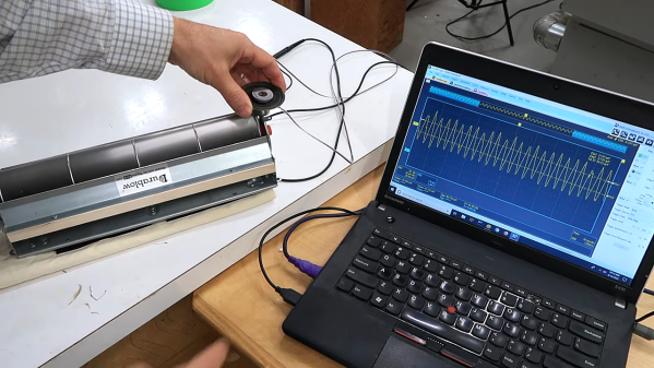
Hooking up a logic analyzer to the “parallel port” on the machine revealed that the device would actually send serial data out over certain pins on the port. The trick that made it harder was that it was in Inverted RS232 form. Thus, all it took was a simple TTL inverter hooked up to a USB-TTL adapter to get the device talking to a modern PC.
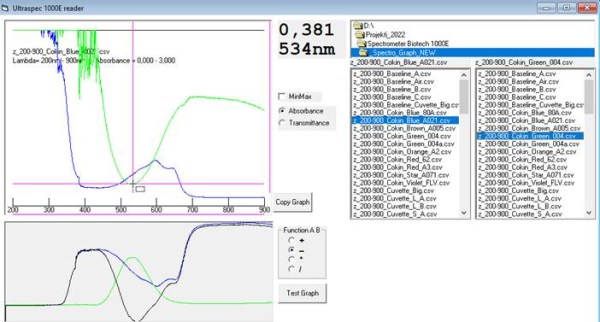
With that achieved, [Jure] was able to whip up a simple VB6 program to collect data from the spectrometer and put it in a CSV file for further analysis. There’s even a program to graph the data right off the bat, making the scientific instrument easier and quicker to use than ever!
Oftentimes, old scientific hardware like this isn’t especially difficult to hack. It’s usually just hard enough to make busy scientists stump up the cash for the fancy adapters and cable, while being no match for the dedicated hacker!