The Internet of Things is getting to be a big business. Google’s Nest brand is part of the trend, and they’re building a product line that fills niches and looks good doing it, including the Nest Protect smoke and CO detector. It’s nice to get texts and emails if your smoke alarm goes off, but if you’d rather not spend $99USD for the privilege, take a look at this $10 DIY smoke alarm interface.
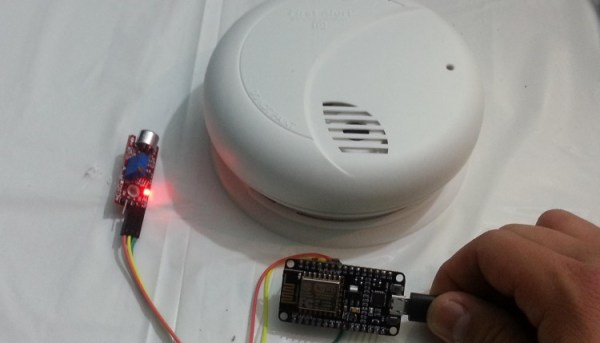
The secret to keeping the cost of [Team SimpleIOThings’] interface at a minimum is leveraging both the dirt-cheap ESP8266 platform and the functionality available on If This Then That. And to keep the circuit as simple and universal as possible, the ESP8266 dev board is interfaced to an existing smoke detector with a simple microphone sensor. From what we can see it’s just a sound level sensor, and that should work fine with the mic close to the smoke detector. But with high noise levels in your house, like those that come with kids and dogs, false alarms might be an issue. In that case, we bet the software could be modified to listen for the Temporal-Three pattern used by most modern smoke detectors. You could probably even add code to send a separate message for a CO detector sounding a Temporal-Four pattern.
Interfacing to a smoke detector is nothing new, as this pre-ESP8266 project proves. But the versatile WiFi SoC makes interfaces like this quick and easy projects.
Continue reading “Audio-coupled Smoke Alarm Interface Sends Texts, Emails”