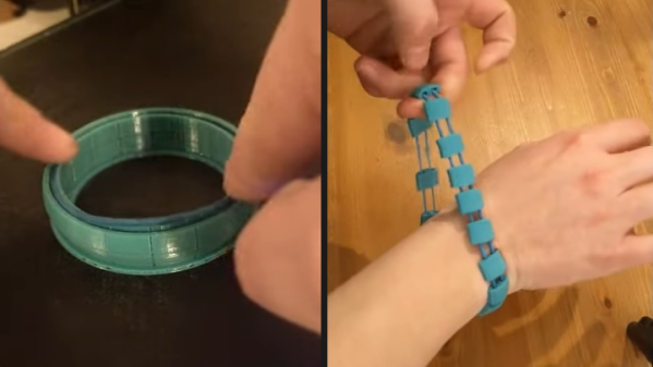
The end result is slightly reminiscent of embedding 3D printed shapes into tulle in order to create fantastic, armor-like flexible creations. But using rubber bands means the result is stretchy and compliant to a degree we haven’t previously seen. Keep it in mind the next time you’re trying to solve a tricky design problem; an embedded o-ring or rubber band might just do the trick.
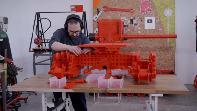
Why did Lego never make MegaTechnic blocks? [Ivan] shows us the true potential of bigger building blocks.The build relies on [Ivan]’s giant 3D-printed Lego-like assembly kit. It lets him simply bolt together a bunch of plastic girders to make the key parts of the excavator, including the base and the digger arm itself. The digger arm is controlled with linear actuators of [Ivan’s] own design, which uses servos and threaded rod to do the job. They’re not as cool as hydraulics or pneumatics, but they get the job done well. For propulsion, [Ivan] built a tracked drive system again using his unique Lego-like blocks. The tracks were tedious to assemble, but add a lot to the excavators Awesomeness Quotient (AQ).
The overall build is quite slow, and more than a little fragile. It’s not quite ready for hardcore digging tasks. In reality, it’s serving as a test bed for [Ivan]’s 3D-printed building blocks that get better every time we see them. Video after the break.
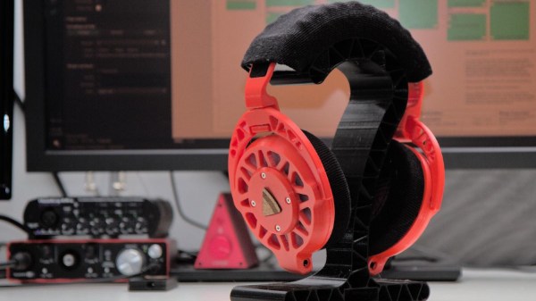
We’ve seen many DIY headphones projects on these fair pages over the years, but not many that are quite as DIY as the Ploopy Headphones. What makes this project interesting is the sheer depth of the construction, with every single part being made from what we might call base materials. Materials such as 3D printer filament, foam and felt, and the usual metallic vitamins.
The electronics are fairly straightforward, with an RP2040 functioning as the USB audio interface and equalizer function. Audio samples are emitted as I2S into a PCM3050 24-bit stereo codec which generates a pair of differential output audio signals. These are then converted from differential to single-ended signals and passed on to the coil drivers. The coil drivers consist of no fewer than eight-paralleled opamps per channel. All of this is powered by the USB-C connection to the host computer. Whilst a kit of parts is available for this, you can make your own if you wish, as the full source (Altium designer needed for tweaks) is available on the Ploopy headphone GitHub.
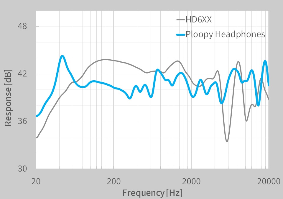
A pretty ploopy response
Many DIY headphone builds would likely be using off-the-shelf speaker units, with large parts of the ear cups being taken from spare parts kits for commercial offerings. But not the Ploopy. The drivers are constructed from flex PCB coils with a standard TRRS jack on each side. Magnets for these coils to react against are held in a 3D-printed frame that is attached to the outer cover. The coils are aligned with a special jig and bonded to the ‘driver foam’ with some 3M VHB tape.
The ear cups are constructed with some 3D printed rings, foam pieces, and simple woven material. The resonator plates push into the inner side of the cup, and the assembly simply screws to the driver assembly. The incredibly detailed assembly wiki makes it look easy, but we reckon there are a few tricky steps in there to trip the unwary. The headband again consists of printed spring sections, some woven material, and foam with a few metallic vitamins thrown in. That makes it sounds simple, but it isn’t.
On the whole the build looks fantastic, but what does it sound like? The Ploopy team has tested them against a pair of Sennheiser HDRXX giving a broadly comparable response, but we’re no audio experts, and the proof, as always, is in the wearing. This project seems to be the ultimate in audio tweakability, with the punchy RP2040 capable of running six audio filters at the full 48 KHz, 16-bit audio, though, the PCM3050 is capable of more.
Want to build some headphones, but need a Bluetooth interface? We got you covered. Can 3D printed headphones ever compare to the big names? We’ll see.
Self-watering planters are low-maintenance, and common DIY projects. What we like most about [Tommy]’s design is that it reuses empty jars to create self-watering planters. After all, jars are fantastic at reliably holding water, so why not put them to work? Incorporating jars as part of the design means fewer worries about leakage, but it also means less 3D printing is needed overall.
A wick (in this case, a piece of string) takes care of moving water from jar to the soil.
[Tommy]’s planter screws onto the threads of a jar’s neck. Getting water to the plant is helped by a small piece of string, which acts as a wick between the soil at the top and the water in the jar at the bottom. This design works best with small plants, but on the plus side there are no moving parts or other complexities. Got a 3D printer? Models for the planter are available here.
The biggest challenge for this design is that not all jar threads are alike, so planters made in this way are not completely interchangeable across all different types of jars. Fortunately, [Tommy] provides the OpenSCAD code he used to generate his design, which he created with the help of an industry guide on how to measure the finish (or threads) of jars and lids.
If you find yourself needing to further customize your own version to fit a particular container’s threads, there’s no need to start from scratch. Unsurprisingly, threads and lids are highly standardized so chances are there exists a calculator, tool, or existing model for exactly what you need.
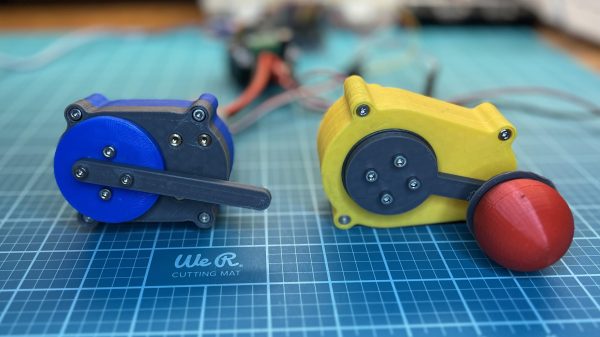
Hobby servos are nifty and useful for a wide range of projects. There’s nothing stopping you from building your own servos though, and you can even give them nifty features like 360-degree rotation In fact, that’s exactly what [Aaed Musa] did!
The servo relies on 3D printed gears in a 3D printed housing. The design makes prodigious use of threaded inserts to hold everything together nice and tight. A DC motor is charged with driving the assembly, as with any regular servo motor. However, in the place of a potentiometer, this design instead uses an AS5600 magnetic rotary position sensor to read the servo’s angle, via a magnet mounted in the servo’s gear. An Arduino is used to determine the servo’s current position versus the desired position, and it turns the motor accordingly with a BTS7960 motor driver.
The result is a sizeable and capable servo with an easily-customizable output, given it’s all 3D printed. If you’d rather just mod some servos instead, we’ve covered some great work in that area, too. Video after the break.
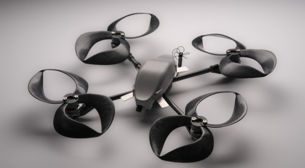
Despite being integral to aviation for more than a century, propellers have changed remarkably little since the Wright Brothers. A team at MIT’s Lincoln Lab has developed a new propeller shape that significantly reduces the noise associated with drones. [PDF via NewAtlas]
Inspired by some of the experiments with “ring wings” in the early 20th Century, researchers iterated on various toroidal propeller geometries until arriving at one that significantly reduces the sound produced by the rotors, particularly in the range of human hearing. The team suspects the reduction in noise is due to vortices being distributed over the whole propeller instead of just the tips.
Experiments show the drones can get twice as close before becoming a nuisance for human ears which should be great news for anyone hoping to launch Skynet commercial drone deliveries. Since the rotors are easily fabricated via 3D printing they should be easy to adapt to a number of different drones.
The toroidal propeller, one of the Lab's @RD100Awards winners, has a unique, closed-form propeller design that makes it a significantly quieter alternative to common multirotor propellers on commercial uncrewed aerial vehicles. https://t.co/hgda3NgYIzpic.twitter.com/5XkIxNVPHd
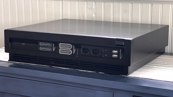
Some careful measuring and a little extra effort can be all that separates what looks like a hack job from a slick end product, and that is apparent in [Eric Sorensen]’s classy retrogaming rig, complete with ports for original console controllers.
Neatly housing these components in a case makes all the difference.
[Eric] likes his vintage gaming, and was terrifically pleased with MiSTer, an open-source project that recreates various classic computers, game consoles and arcade machines using modern FPGA-based hardware. Of course, what makes retro gaming even better is using a platform’s genuine original controllers, which just takes a little extra hardware and wiring.
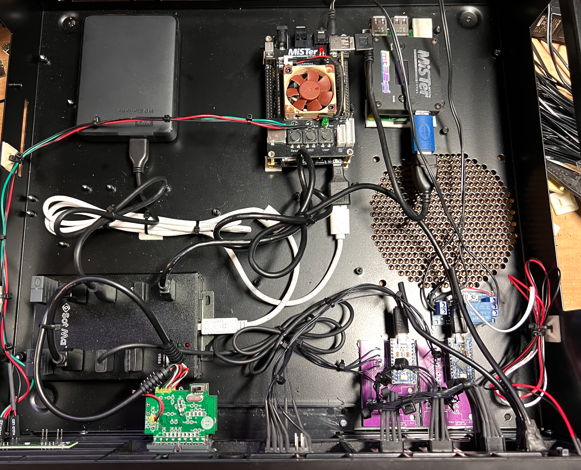
But [Eric] found that all the required accessories and peripherals started to look awfully cluttered. He solved this issue by packing everything carefully into a specialty PC case called the Checkmate A1500 Plus, which gives off a strong 80s design vibe. As a bonus, the front panels are all removable and that’s where [Eric] decided to house the custom controller ports.
First [Eric] carefully measured each controller connector to create CAD models, then designed matching front panels to house the connectors and 3D printed them. Once that was done, post-processing the panels was a long process of apply Bondo, sand, paint, and repeat as needed. The results looks fantastic, and this project is a prime example of how aesthetics and finish can matter.