At even vaguely infosec-related conferences, CTFs are a staple. For KernelCon 2021, [Tyler Rosonke] resolved to create a challenge breaking the traditions, entertaining and teaching people in a different way, while satisfying the constraints of that year’s remote participation plans. His imagination went wild in all the right places, and a beautifully executed multi-step hardware challenge was built – only in two copies!
Story behind the challenge? Your broken spaceship has to be repaired so that you can escape the planet you’re stuck on. The idea was to get a skilled, seasoned hacker solving challenges for our learning and amusement – and that turned out to be none other than [Joe “Kingpin” Grand]!
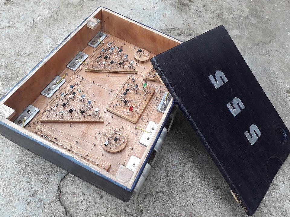
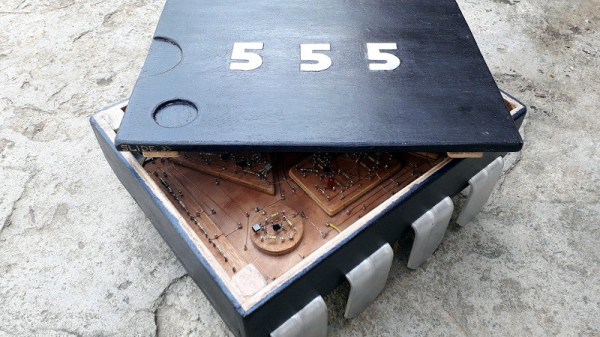
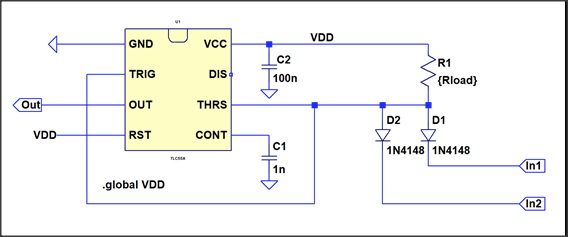
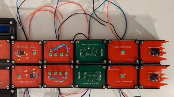
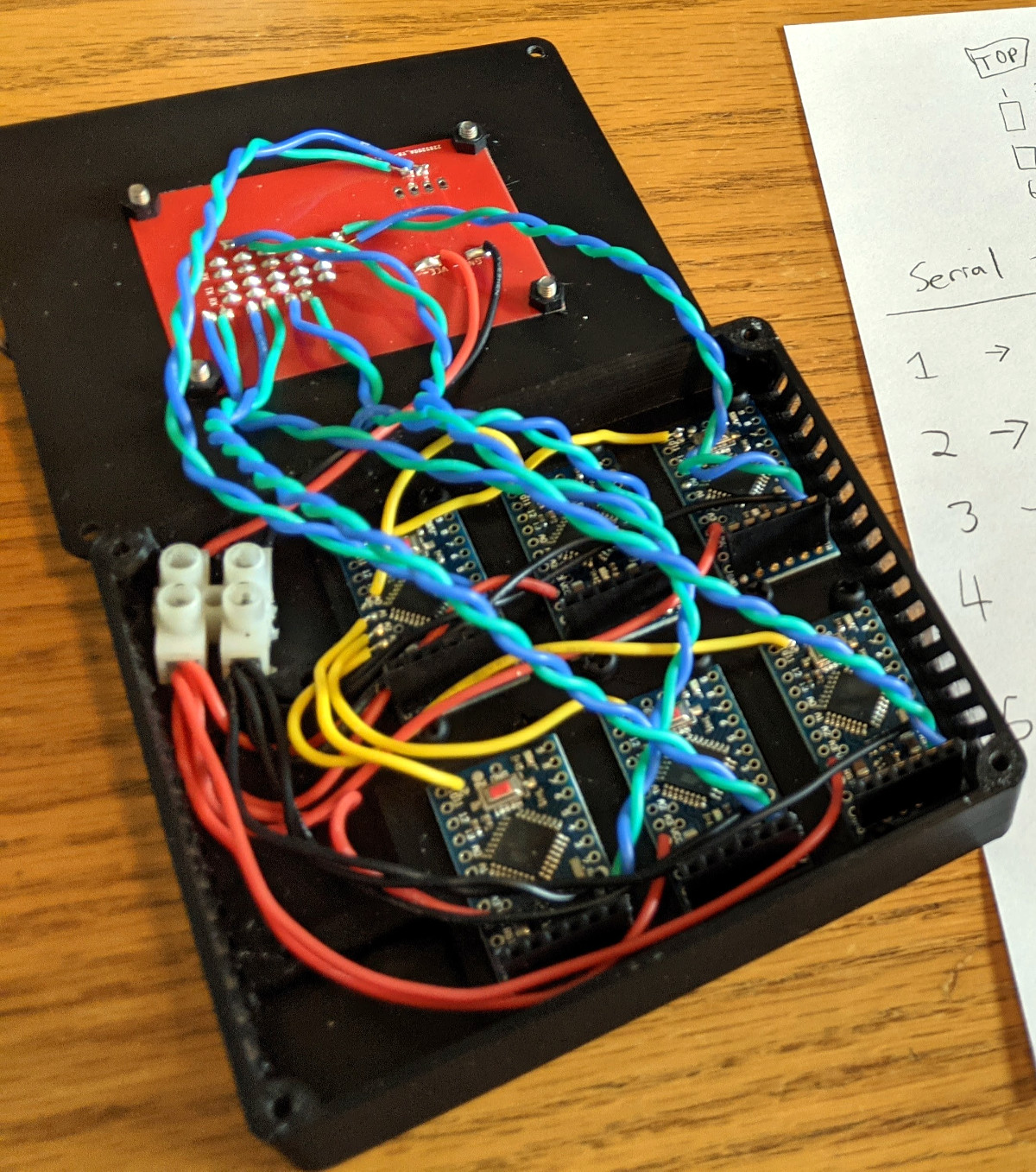 The modules themselves are what caught our attention. Designed to cover a wide array of hardware hacker skills, they cover soldering, signal sniffing, logic gates, EEPROM dumping and more – and you have to apply all of these successfully for liftoff. If you thought “there’s gotta be a 555 involved”, you weren’t wrong, either, there’s a module where you have to reconfigure a circuit with one!
KernelCon is a volunteer-driven infosec conference in Omaha, and its 2022 installment starts in a month – we can’t wait to see what it brings! Anyone doing hardware CTFs will have something to learn from their stories, it seems. The hacking session, from start to finish, was recorded for our viewing pleasure; linked below as an hour and a half video, it should be a great background for your own evening of reverse-engineering for leisure!
This isn’t the first time we’ve covered [Tyler]’s handiwork, either. In 2020, he programmed a batch of KernelCon badges while employing clothespins as ISP clips. Security conferences have most certainly learned just how much fun you can have with hardware, and if you ever need a case study for that, our review of 2019 CypherCon won’t leave you hanging.
Continue reading “Spaceship Repair CTF Covers Hardware Hacker Essentials”