Necessity might be the mother of all invention, but we often find that inventions around here are just as often driven by expensive off-the-shelf parts and a lack of willingness to spend top dollar for them. More often than not, we find people building their own tools or parts as if these high prices are a challenge instead of simply shrugging and ordering them from a supplier. The latest in those accepting the challenge of building their own parts is [Advanced Tinkering] who needed a specialty pressure gauge for a vacuum chamber.
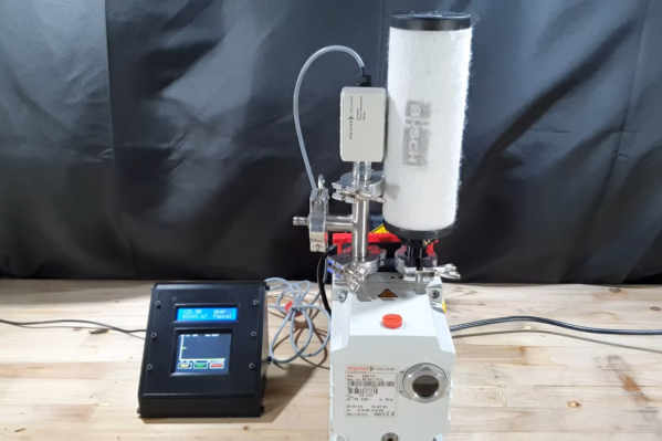
In this specific case, the sensor itself is not too highly priced but the controller for it was the deal-breaker, so with a trusty Arduino in hand a custom gauge was fashioned once the sensor was acquired. This one uses an external analog-to-digital converter to interface with the sensor with 16-bit resolution, along with some circuitry to bring the ~8 V output of the sensor down to the 5 V required by the microcontroller. [Advanced Tinkering] wanted a custom live readout as well, so a 3D printed enclosure was built that includes both an LCD readout of the pressure and a screen with a graph of the pressure over time.
For anyone else making sensitive pressure measurements in a vacuum chamber, [Advanced Tinkering] made the project code available on a GitHub page. It’s a great solution to an otherwise overpriced part provided you have the time to build something custom. If you’re looking for something a little less delicate, though, take a look at this no-battery pressure sensor meant to ride along on a bicycle wheel.