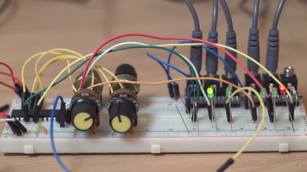
We’d seen it done with buttons, switches, gestures, capacitive touch, and IR remote, but never like this. [electron_plumber] made an LED that can be blown out like a candle, and amazingly it requires no added sensors. The project uses an Arduino to demonstrate turning a tiny LED on and off in response to being blown on, and the only components are the LED and a resistor.
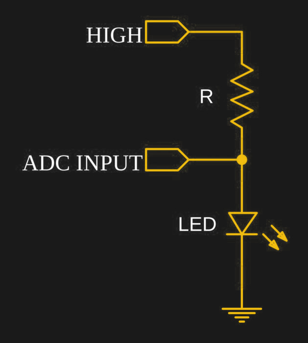
It’s a clever demo with a two important details to make it work. The first is the LED itself; [electron_plumber] uses a tiny 0402 LED that is mounted on two wires in order to maximize the temperature change caused by blowing on it. The second is the method for detecting changes of only a few millivolts more reliably. By oversampling the Arduino’s ADC, an effectively higher resolution is obtained without adding any hardware or altering the voltage reference. Instead of reading the ADC once, the code reads the ADC 256 times and sums the readings. By working with the larger number, cumulative changes that would not register reliably on a single read can be captured and acted upon. More details are available from [electron_plumber]’s GitHub repository for LEDs as Sensors.
Embedded below is a video that is as wonderful as it is brief. It demonstrates the project in action, takes a “show, don’t tell” approach, and is no longer than it needs to be.
Continue reading “An LED You Can Blow Out, With No Added Sensor”