Home weather stations are a great way for hackers and makers to put their skills to practical use. After all, who wants to hear the current conditions for the whole city when they could setup their own station which drills that information down to their very own street? Such a setup doesn’t need to be any more complex than a temperature sensor wired up to a microcontroller, but then not all of us are quite the weather fanatic that [Richard] clearly is.
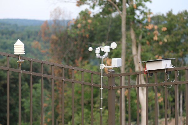
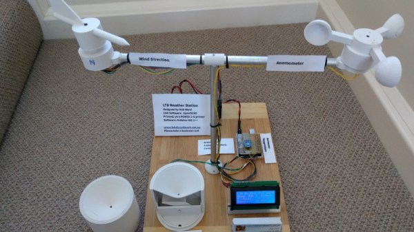
The system he’s built to monitor the wind over his home is, to put it mildly, incredible. We might not all share the obsession [Richard] apparently has with the wind, but we can certainly respect the thought and design that went into this comprehensive system. From his scratch built anemometer to the various ways he’s come up with to display the collected environmental data throughout his home, if this build doesn’t inspire you to hack together your own weather station then nothing will.
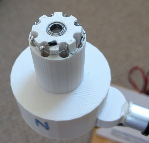
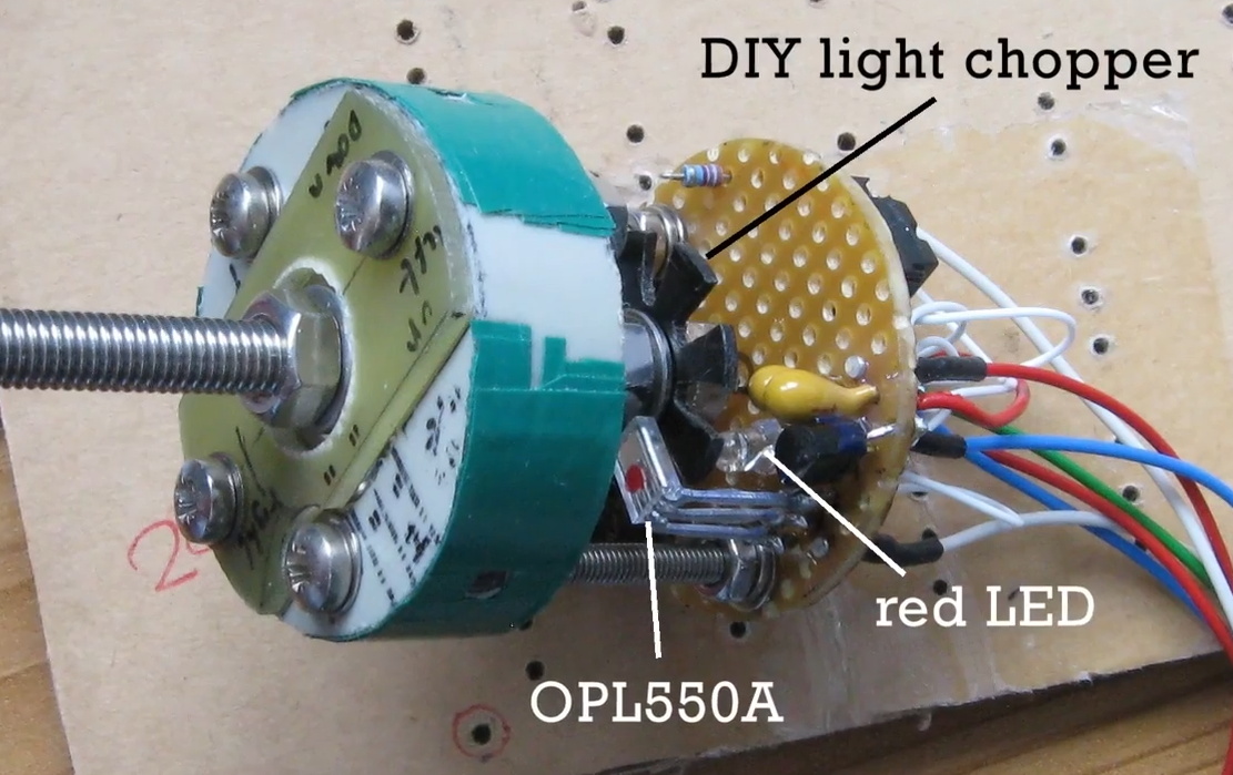 At the heart of the system is the anemometer itself, which makes use of several scavenged parts such as the bottom halves of plastic Easter eggs as wind cups. The cups spin on a short length of M5 threaded rod inside of a 635ZZ bearing, which ultimately rotates a “light chopper” placed between a red LED and a OPL550A optical sensor. In a particularly nice touch, [Richard] has even included a few power resistors arranged around the moving parts to use as a heater which keeps the device from freezing up when the temperature drops. The sensor creates eight digital pulses per revolution, and feeds data into the base station though a 30 meter (98 feet) cable.
From there, the base station uses an ESP8266 to upload wind and temperature data to ThingSpeak and Weather Underground to be viewed through their respective web interfaces and applications. The project really could have ended here and still been impressive in its own right, but the station also includes 433 MHz and NRF24L01 transmitters to send the data to the other display devices which [Richard] has designed.
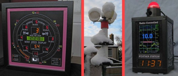
The 433 MHZ display is built into the frame of a lantern, and shows the current time and temperature on an LED readout as well as historical wind and temperature graphs on a 2.2 inch ILI9341 TFT screen which [Richard] has rotated into a portrait layout. There’s a red light on top that blinks whenever a signal is received to show that the system is working, and even a touch sensor which can be used to turn off the TFT screen at a tap if you’re not interested in seeing the full charts.


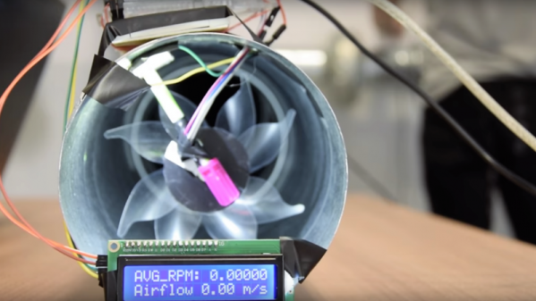
The other display, which [Richard] calls the “picture frame” utilizes a dizzying array of single LEDs, a handful of digital LED readouts, and even an OLED screen for good measure. They all work together to show the current wind speed as well the averages for the past day in three hour segments. As this display features a real time display of current wind conditions and averages for as short a period of two minutes, it uses the NRF24L01 receiver to get data from the base station at a rate of 3 Hz.
In the past we’ve seen 3D printed weather stations, and of course some pretty simple affairs using little more than an ESP8266 board and some sensors. But few have ever put so much thought into how to present the collected data to the user. If you’re serious about knowing what it’s like outside the confines of your bunker, [Richard] has got some tricks to show you.

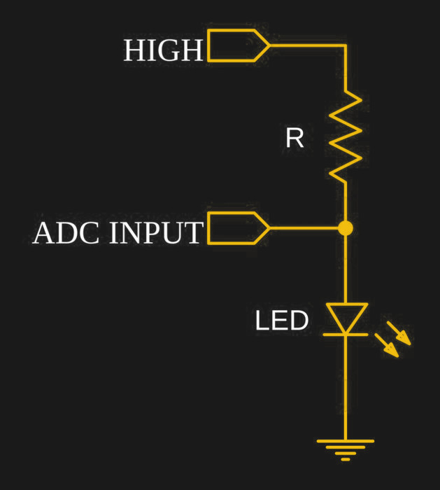


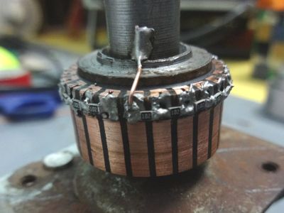 We have to admit that when we first saw [Ajoy Raman]’s Instructables post, we figured that he used a universal motor to generate a voltage from the anemometer. But [Ajoy]’s solution to the coaxial shafts problem is far more interesting than that. A discarded universal motor donated its rotor and bearings. The windings were stripped off the assembly leaving nothing but the commutator. 1kΩ SMD resistors were soldered across adjacent commutator sections to form a series resistance of 22kΩ with taps every 1k, allowing 0 to 2.2V to be read to the ADC of a microcontroller depending on the angle of the vane.