Care to flex your ethical hacker muscles? The Defense Advanced Research Projects Agency, better known as DARPA, is running its first-ever bug-bounty program. The event is called “Finding Exploits to Thwart Tampering”, or FETT — get it? Bounty hunter? Fett? — and is designed to stress-test security hardware developed through DARPA’s System Security Integration Through Hardware and Firmware, or SSITH. Tortured backronyms and pop culture references aside, FETT will start this month and go through September. This is not an open challenge per se; rather, the Red Team will be coordinated by crowdsourced security research company Synack, who has called for security researchers to sign on.
The Linux kernel development team has decided to join the trend away from insensitive terminology like “master/slave” and “blacklist/whitelist” in coding style. A July 4 proposal by kernel maintainer Dan Williams goes into some detail on the logic of making the change, and it’s quite convincing stuff. It’s hard to argue with the fact that code reviewers can easily be distracted by coding style changes, so replacing terms that have become lightning rods only makes sense. Linus himself has signed off on the changes for all future code; the current terminology will only be allowed for purposes of maintaining older code.
Some stories just leap off the screen when you’re scanning headlines, and a story with the term “narco-antennas” practically begs further investigation. It turns out that the drug cartels in Mexico (and probably elsewhere, but the story focused on Mexico) are quite sophisticated in terms of communications technology. Eschewing cell phones for some of their communication needs for obvious reasons, they still apparently leverage the cell system by installing their own transceivers at cell sites. This can lead to some tense moments for the engineers who maintain legitimate gear at these sites; the story above recounts one hapless tech who powered down a site to make some repairs only to be confronted by armed men upset about the loss of their radios. It’s a fascinating look at the underworld and their technology, and we can’t help but feel for the men and women who have to face down these criminals just to do their jobs.
Way back in January — remember January? — we kicked off the 2020 Hack Chat series with a fellow named Alberto Caballero, principal investigator of the Habitable Exoplanet Hunting Project. At the time, I was blown away by the fact that the tiny changes in intensity caused by planets transiting across their star’s face were detectable on Earth with instruments an amateur astronomer could easily afford. And now, the project’s crowdsourced planet hunters have hit pay dirt, with the discovery of a Saturn-sized exoplanet in orbit within the habitable zone around star GJ 3470, also known as Gliese 3470, a red dwarf about 30 parsecs away in the constellation Cancer. Their paper is still in preprint and hasn’t been peer-reviewed yet, but it’s exciting to see this kind of citizen science being done, and we’d like to congratulate the team on their achievement and wish them continued luck in their search for “Earth 2.0”
And finally, if you can’t stand the idea that future archaeologists may someday pore over your code in an attempt to understand the digital lives of their long-dead forebears, then you might want to skip this story about how GitHub shipped 21 terabytes of open-source code to cold storage. The destination for the data, contained on reels of archive film and shipped on two pallets, is the world’s long-term memory: the Artic World Archive on the island of Svalbard. Perhaps better known for the Svalbard Seed Vault, where the genetic diversity of the world’s plants is stored, the Artic Code Vault is in a nearby abandoned coal mine and set deep within the permafrost. The rationale for making the effort to preserve code makes for some interesting reading, but we can’t help but feel that like the graffitists of Pompeii, if we’d known someone would be reading this stuff in a thousand years, we might have edited out a few things.
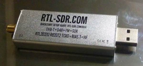
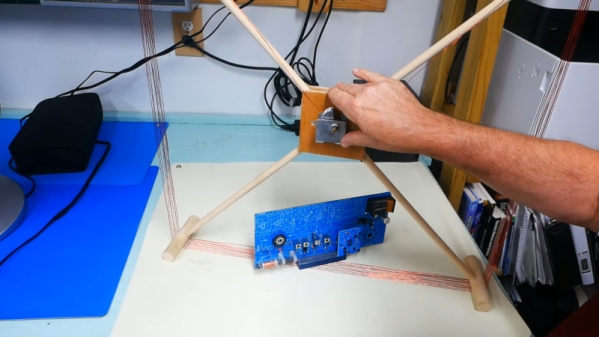
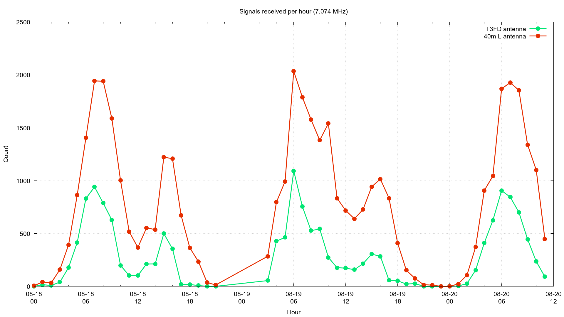 Data for each received FT8 transmission was recorded to a log file. [Eric] also modified GQRX and WSJT-X to give him all the remote control features he needed to automatically change frequencies. Between the two antenna setups, more than 100,000 FT8 transmissions were logged. Using the recorded data and Python he compared the number of received transmissions, the distance, and the heading to the transmitters, using the location information included in many FT8 transmissions. Where the same transmission was received by both antennas, the signal-to-noise ratios was compared.