Thermal Printer Brain Transplant

Thermal Printer Brain Transplant Is Two Hacks In One

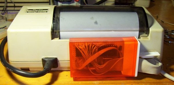
You know how sometimes you just can’t resist collecting old hardware, so you promise yourself that you will get around to working on it some day? [Danny] actually followed through on one of those promises after discovering an old Radio Shack TRS-80 TP-10 thermal printer in one of his boxes of old gear. It looks similar to a receipt printer you might see printing receipts at any brick and mortar store today. The original printer worked well enough, but [Danny] wasn’t satisfied with its 32 character per line limitation. He also wanted to be able to print more complex graphics. To accomplish this goal, he realized he was going to have to give this printer a brain transplant.

First, [Danny] wanted to find new paper for the printer. He only had one half of a roll left and it was 30 years old. He quickly realized that he could buy thermal paper for fax machines, but it would be too wide at 8.5 inches. Luckily, he was able to use a neighbor’s saw to cut the paper down to the right size. After a test run, he knew he was in business. The new fax paper actually looked better than the old stuff.

The next step was to figure out exactly how this printer works. If he was going to replace the CPU, he was going to need to know exactly how it functioned. He started by looking at the PCB to determine the various primary functions of the printer. He needed to know which functions were controlled by which CPU pins. After some Google-Fu, [Danny] was able to find the original manual for the printer. He was lucky in that the manual contained the schematic for the circuit.

Once he knew how everything was hooked up, [Danny] realized that he would need to learn how the CPU controlled all of the various functions. A logic analyzer would make his work much easier, but he didn’t happen to have one lying around. [Danny] he did what any skilled hacker would do. He built his own!

He built the analyzer around an ATMega664. It can sample eight signals every three microseconds. He claims it will fill its 64k of memory in about one fifth of a second. He got his new analyzer hooked up to the printer and then got to work coding his own logic visualization software. This visualization would provide him with a window to the inner workings of the circuit.

Now that he was able to see exactly how the printer functioned, [Danny] knew he would be able to code new software into a bigger and badder CPU. He chose to use another ATMega microcontroller. After a fair bit of trial and error, [Danny] ended up with working firmware. The new firmware can print up to 80 characters per line, which is more than double the original amount. It is also capable of printing simple black and white graphics.

[Danny] has published the source code and schematics for all of his circuits and utilities. You can find them at the bottom of his project page. Also, be sure to catch the demonstration video below. Continue reading “Thermal Printer Brain Transplant Is Two Hacks In One”

Demystifying NTSC Color And Progressive Scan

NTSC

Black and white NTSC is simple – it can, and was, done with vacuum tubes for a long, long time. Color is just weird, though. It runs at 29.976 frames per second, uses different phases of the carrier for different colors, and generally takes a while to wrap your head around. [Sagar] is doing a series on the intricacies of NTSC, and the latest post deals with color and progressive scanning versus interlacing, or as it is better known, how classic game consoles and home computers generate video.

The test bed for [Sagar]’s video experimentations is a circuit containing an ATMega16, a 4-bit shift register, and a 14.31818 MHz clock. This clock is much faster than the 3.579545 MHz clock in an NTSC carrier frequency – exactly four times as fast – allowing the shift register to output four different phases of the carrier frequency a 0°, 90°. 180°, and 270°. Playing with some of the pins on the ATMega in the circuit results in a palette being generated on any old TV.

NTSC requires interlaced scanning, or sending an entire screen of even lines, then an entire screen of odd lines, at around 60 fields per second. The Nintendos and Segas of yesteryear didn’t bother with this, instead opting to send half the vertical resolution at double the frame rate. This is known as a progressive scan. [Sagar] found that this resulted in some image artifacts when displayed on a modern LCD, and moving back to an interlaced mode fixed the problem. All the code and files are up on the gits. If you’re feeling adventurous, this is exactly how projects like the Uzebox have created homebrew game consoles using little more than the ATMega found in [Sagar]’s build.

Pinoccio: Mesh All The (Internet Of) Things

PinnThere’s a problem with products geared towards building the Internet of Things. Everyone building hardware needs investors, and thus some way to monetize their platform. This means all your data is pushed to ‘the cloud’, i.e. a server you don’t own. This is obviously not ideal for the Hackaday crowd. Yes, IoT can be done with a few cheap radios and a hacked router, but then you don’t get all the cool features of a real Things project – mesh networking and a well designed network. Pinoccio is the first Thing we’ve seen that puts a proper mesh network together with a server you can own. The Pinoccio team were kind enough to let us drop in while we were in Rock City last weekend, and we were able to get the scoop on these tiny boards from [Sally] and [Eric], along with a really cool demo of what they can do.
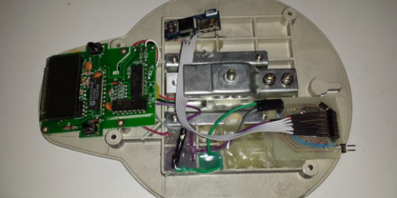
The hardware on the Pinoccio is basically an Arduino Mega with a LiPo battery and an 802.15.4 radio provided by an ATmega256RFR2. The base board – technically called a ‘field scout’ – can be equipped with a WiFi backpack that serves as a bridge for the WiFi network. It’s a pretty clever solution to putting a whole lot of Things on a network, without having all the Things directly connected to the Internet.

Programming these scouts can be done through Arduino, of course, but the folks at Pinoccio also came up with something called ScoutScript that allows you to send commands directly to any or all of the scouts on the mesh network. There’s a neat web-based GUI called HQ that allows you to command, control, and query all the little nodules remotely as well.

In the video below, [Sally] goes over the basic functions of the hardware and what it’s capable of. [Eric] was in Reno when we visited, but he was kind enough to get on a video chat and show off what a network of Pinoccios are capable of by emblazoning their web page with Hackaday logos whenever he presses a button.

Continue reading “Pinoccio: Mesh All The (Internet Of) Things”

Add A Bluetooth Interface To Your Kitchen Scale

Kitchen scale

When [Adam] found himself in need of a force meter, he didn’t want to shell out the cash for a high-end model. Instead, he realized he should be able to modify a simple and inexpensive kitchen scale to achieve the results he desired.

The kitchen scale [Adam] owned was using all through hole components on a double-sided PCB. He was able to easily identify all of the IC’s and find their datasheets online. After doing some research and probing around with a frequency counter, he realized that one of the IC’s was outputting a frequency who’s pulse width was directly proportional to the amount of weight placed on the scale. He knew he should be able to tap into that signal for his own purposes.

[Adam] created his own custom surface mount PCB, and used an ATMega8 to detect the change in pulse width. He then hooked up a Bluetooth module to transmit the data wirelessly. These components required no more than 5V, but the scale runs from two 3V batteries. Using what he had on hand, [Adam] was able to lower the voltage with just a couple of diodes.

[Adam] managed to cram everything into the original case with little modification. He is now considering writing an Android application to interface with his upgraded kitchen scale.

Handheld Game System Powered By Arduino

DIY Handheld Game System

These days, it’s easy enough to play games on the go. If you have a smart phone, you are pretty much set. That doesn’t mean you can’t still have fun designing and building your own portable gaming system, though.

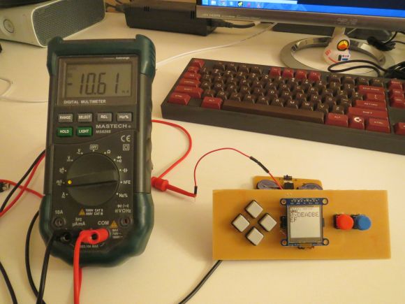
[randrews] did just that. He started out by purchasing a small memory LCD display from Adafruit. The screen he chose is low power as far as screens go, so it would be a good fit for this project. After testing the screen with a quick demo program, it was time to start designing the circuit board.

[randrews] used Eagle to design the circuit. He hand routed all of the traces to avoid any weird issues that the auto router can sometimes cause. He made an efficient use of the space on the board by mounting the screen over top of the ATMega chip and the other supporting components. The screen is designed to plug in and out of the socket, this way it can be removed to get to the chip. [randrews] needs to be able to reach the chip in order to reprogram it for different games.

Once the board design was finished, [randrews] used his Shapeoko CNC mill to cut it out of a copper clad board. He warns that you need to be careful doing this, since breathing fiberglass dust is detrimental to living a long and healthy life. Once the board was milled out, [randrews] used a small Dremel drill press to drill all of the holes.

The final piece of the puzzle was to figure out the power situation. [randrews] designed a second smaller PCB for this. The power board holds two 3V coin cell batteries. The Arduino expects 5V, so [randrews] had to use a voltage regulator. This power board also contains the power switch for the whole system.

The power board was milled and populated. Then it was time to do some measurements. [randrews] measured the current draw and calculates that he should be able to get around 15 hours of play time using the two 3V coin cell batteries. Not bad considering the size.

[via Reddit]

640×480 VGA On An Arduino

There are dozens, if not hundreds of examples around the Intertubes of an Arduino generating a VGA video output. The Arduino isn’t the fastest chip by far, and so far, all of these VGA generation techniques have peaked out at lower resolutions if you want to control individual pixels.[PK] has an interesting technique to generate 640×480 VGA at 60 frames per second without overclocking. It’s hacky, it’s ugly, but surprisingly, it actually works.

The VGA standard of 640×480 @ 60 fps requires pixels to be clocked out at 25.175 MHz, and the ATMega chips found in Arduinos top out at 20 MHz. [PK] wanted to generate VGA signals without overclocking, He did this by doubling the clock frequency with digital logic. The ATMega generates a clock, an inverter delays that clock so it is 90 degrees out of phase, and the two clocks are XORed, doubling clock output of the micro. It produces a very ugly square wave at 32 MHz – an error of 27% compared to the VGA spec. Somehow it still works.

With a hilariously out of spec clock, the rest of the project was pulled together from [Nick Gammon]’s VGA library, a 16×16 font set, and a project from [lft]. Video below.

Continue reading “640×480 VGA On An Arduino”

The Most Random Electronic Dice Yet

di

If you’ve written a great library to generate random numbers with a microcontroller, what’s the first thing you would do? Build an electronic pair of dice, of course.

[Walter] created the entropy library for AVRs for a reliable source of true random numbers. It works by using the watchdog timer’s natural jitter; not fast by any means but most sources of entropy aren’t that fast anyway. By sampling a whole lot of AVR chips and doing a few statistical tests, it turns out this library is actually a pretty good source of randomness, at least as good as a pair of dice.

The circuit itself uses two 8×8 LED matrices from Adafruit, an Arduino, and a pair of buttons. The supported modes are 2d6, 2d4, 2d8, 2d10, 1d12, 1d20, a deck of cards, a single hex number, a single 8-bit binary number, or an eight character alphanumeric password. It’s more than enough for D&D or when you really need an unguessable password. Video demo below.

Continue reading “The Most Random Electronic Dice Yet”