Adding Bluetooth To Original SNES Controllers

There’s a bunch of companies selling wireless Super Nintendo style controllers out there. You can go on Amazon and get any number of modern pads that at least kinda-sorta look like what came with Nintendo’s legendary 1990’s game console. They’ve got all kinds of bells and whistles, Bluetooth, USB-C, analog sticks, etc. But none of them are legitimate SNES controllers, and for some people that’s just not good enough.

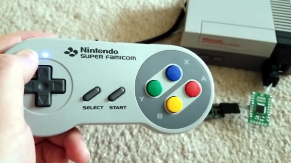
[sjm4306] is one of those people. He wanted to add Bluetooth and some other modern niceties to a legitimate first-party SNES controller, so he picked up a broken one off of eBay and got to work grafting in his custom hardware. The final result works with Nintendo’s “Classic Edition” consoles, but the concept could also work with the original consoles as well as the computer if you prefer your classic games emulated.

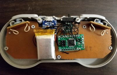
A custom ATMEGA328P-powered board polls the controller’s SPI serial shift register in much the same way the original SNES would have. It then takes those button states and sends them out over UART with a HC-05 Bluetooth module. The controller is powered by a 330 mAh 3.7V battery, and a charging circuit allows for easily topping the controller off with a standard USB cable.

A particularly nice touch on the controller is the use of custom light pipes for the status LEDs. [sjm4306] made them by taking pieces of transparent PLA 3D printer filament, heating and flattening the end, and then sanding it smooth. This provides a diffusing effect on the light, and we’ve got to say it looks very good. Definitely a tip to file away for the future.

On the receiving side, this project was inspired by a custom NES Classic Edition Advantage controller we featured last year, and borrows the work creator [bbtinkerer] did to get his receiver hardware talking to the Classic console over I2C.

We’ve seen a number of projects which have added wireless functionality to the classic Super Nintendo controller, but most tend to be more invasive than this one. We like the idea of reading the controller’s original hardware rather than completely gutting it.

Continue reading “Adding Bluetooth To Original SNES Controllers”

DIY Arduino Soldering Iron Hits Version 2.0

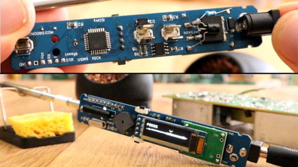
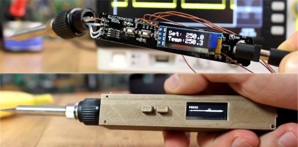
A few months ago we brought word that [Electronoobs] was working on his own open source alternative to pocket-sized temperature controlled soldering irons like the TS100. Powered by the ATMega328p microcontroller and utilizing a 3D printed enclosure, his version could be built for as little as $15 USD depending on where you sourced your parts from. But by his own admission, the design was held back by the quality of the $5 replacement soldering iron tips he designed it around. As the saying goes, you get what you pay for.

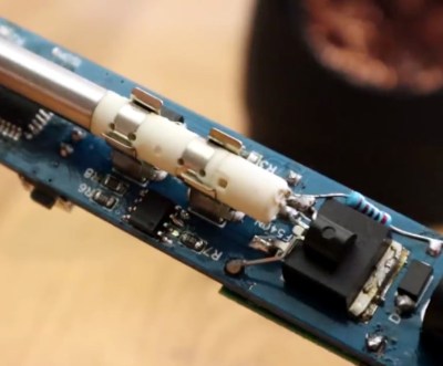
But [Electronoobs] is back with the second version of his DIY portable soldering iron, and this time it’s using the vastly superior HAKKO T12 style tip. As this tip has the thermocouple and heating element in series it involved a fairly extensive redesign of the entire project, but in the end it’s worth it. After all, a soldering iron is really only as good as its tip to begin with.

This version of the iron deletes the MAX6675 used in V1, and replaces it with a LM358 operational amplifier to read the thermocouple in the T12 tip. [Electronoobs] then used an external thermocouple to compare the LM358’s output to the actual temperature at the tip. With this data he created a function which will return tip temperature from the analog voltage.

While the physical and electrical elements of the tip changed substantially, a lot of the design is still the same from the first version. In addition to the ATMega328p microcontroller, version 2.0 of the iron still uses the same 128×32 I2C OLED display, MOSFET, and 5V buck converter from the original iron. That said, [Electronoobs] is already considering a third revision that will make the iron even smaller by replacing the MOSFET and buck converter. It might be best to consider this an intermediate step before the DIY iron takes on its final form, which we’re very interested in seeing.

The first version of the DIY Arduino soldering iron garnered quite a bit of attention, so it seems there’s a decent number of you out there who aren’t content with just plunking down the cash for the TS100.

Continue reading “DIY Arduino Soldering Iron Hits Version 2.0”

An Arduino Watch Without A Clock

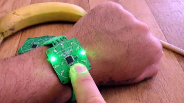
When you show up at a party wearing this bare PCB watch, there are effectively two possible reactions you might receive from the other people there. Either they are going to snicker at the nerd who’s wearing a blinking circuit board on their wrist in public, or they are going to marvel at the ridiculously low part count. We’ll give you one guess as to which reaction you’d likely get at any event Hackaday is involved in.

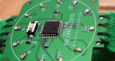
Designed and built by [Electronoobs], this extremely simple watch consists of a ATmega328P microcontroller, a dozen LEDs with their associated 200 Ω resistors, and a battery. There’s also a single push button on the front which is used to not only set the watch, but turn the LEDs on when you want to check the time. Short of dropping down to one LED and blinking out the time, it’s hard to imagine a timepiece with fewer components than this.

You’re probably wondering how [Electronoobs] pulled this off without an external clock source for the ATmega328P chip. The chip actually has an internal 8 MHz oscillator that can be used, but you need to flash the appropriate bootloader to it first. Accordingly, the backside of the PCB has both SPI and a UART solder pads for external bootloader and firmware programming.

As you might expect, there’s a downside to using the internal oscillator: it’s not very good. The ATmega328P spec sheet claims a factory calibrated accuracy of ±10%, and [Electronoobs] has found that equates to a clock drift of around 15 seconds per day. Not exactly great, but considering the battery only lasts for two days anyway, it doesn’t have much of an impact in this case.

Compared to other “analog” LED watches we’ve seen, the simplicity of this build is really quite remarkable. The closest competitor we’ve seen so far is this slick binary watch.

Continue reading “An Arduino Watch Without A Clock”

Build Your Own Portable Arduino Soldering Iron

At this point you’ve almost certainly seen one of these low-cost portable soldering irons, perhaps best exemplified by the TS100, a pocket-sized temperature controlled iron that can be had for as little as $50 USD from the usual overseas suppliers. Whether or not you’re personally a fan of the portable irons compared to a soldering station, the fact remains that these small irons are becoming increasingly popular with hackers and makers that are operating on a budget or in a small workspace.

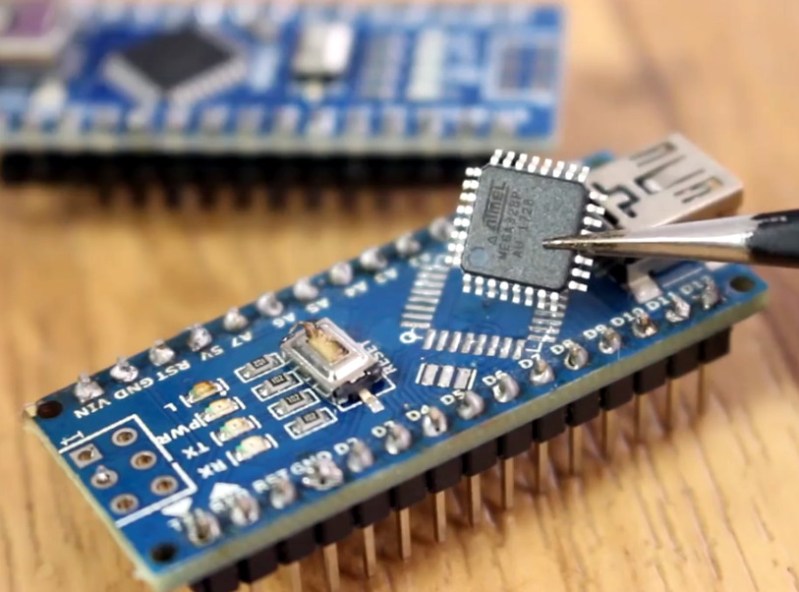
Believing that imitation is the most sincere form of flattery, [Electronoobs] has come up with a DIY portable soldering iron that the adventurous hacker can build themselves. Powered by an ATMega328p pulled out of an Arduino Nano, if offers the same software customization options of the TS100 but at a considerably lower price. Depending on where you source your components, you should be able to build one of these irons for as little as $15.

The iron features a custom PCB and MAX6675 thermocouple amplifier to measure tip temperature. A basic user interface is provided by two tactile buttons on the PCB as well as an 128×32 I2C OLED display. In a future version, [Electronoobs] says he will look into adding some kind of sensor to detect when the iron is actually being used and put it to sleep when inactive.

The tip is sourced from a cheap soldering station replacement iron, and according to [Electronoobs], is probably the weakest element of the entire build. He’s looking into using replacement TS100 tips, but says he’ll need to redesign his electronics to make it compatible. The case is a simple 3D printed affair, which looks solid enough, but seems likely to be streamlined in later versions.

We’ve seen a number of attempts at DIY soldering irons over the years, but we have to say, this one is probably the most professional we’ve ever seen. It will be interesting to see how future revisions improve on this already strong initial showing.

Continue reading “Build Your Own Portable Arduino Soldering Iron”

The A To Z Of Building Your Own Keyboard

We’ve featured a number of people who’ve taken the plunge and created their own customized keyboard; at this point it’s safe to say that there’s enough information and source code out there that anyone who’s looking to build their own board won’t have much trouble figuring out how to do so. That being said, it’s nice to have a comprehensive at a process from start to finish. Why sift through forum posts and image galleries looking for crumbs if you don’t have to?

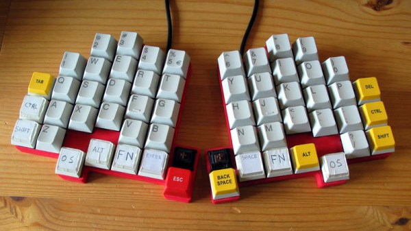
That’s precisely what makes this write-up by [Maarten Tromp] so interesting. He walks the reader through every step of the design and creation of his customized keyboard, from coming up with the rather unique layout to writing the firmware for its AVR microcontroller. It’s a long read, filled with plenty of tips and tricks from a multitude of disciplines.

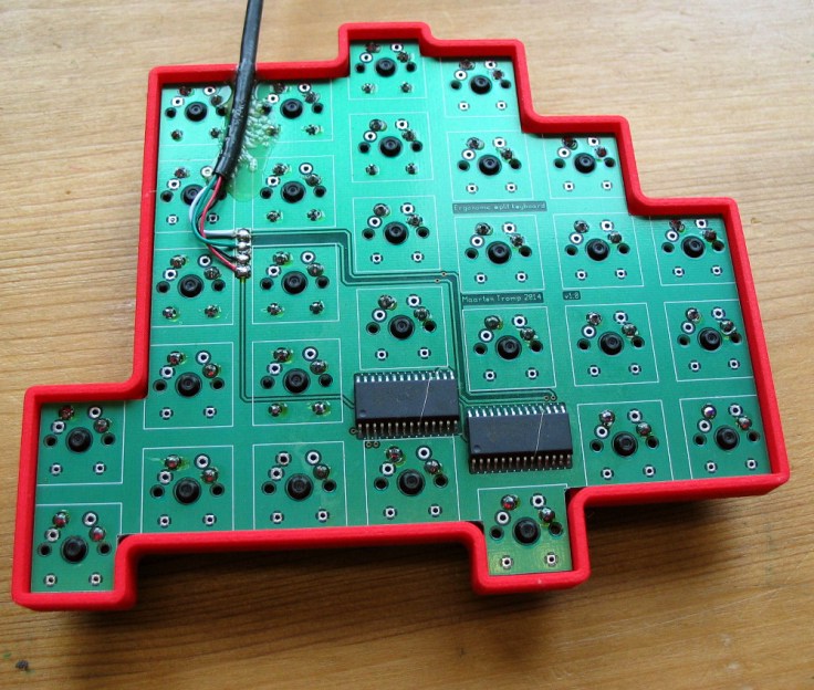
After looking at other custom boards for inspiration, [Maarten] used OpenSCAD to create a 3D model of his proposed design, and had it printed at Shapeways. His electronics are based around an Atmel ATMega328P using vUSB, and Microchip MCP23017 I/O expanders to connect all the keys. He wrapped it all up by designing a PCB in gEDA PCB and having it sent off for production. As a testament to his attention to detail, everything mated up on the first try.

[Maarten] is happy with the final product, but mentions that in a future revision he would like to add RGB lighting and use a microcontroller that has native USB support. He’d also like to drop the I/O expanders and switch over to Charlieplexing for the key matrix.

From uncommon layouts to diminutive technicolor beauties, it seems there’s no end of custom keyboards in sight. We aren’t complaining.

Don’t Flake On Your Fish—Feed Them Automatically

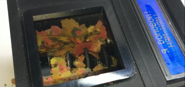
We get it. You love your fish, but they can’t bark or gently nip at your shin flesh to let you know they’re hungry. (And they always kind of look hungry, don’t they?) One day bleeds into the next, and you find yourself wondering if you’ve fed them yet today. Or are you thinking of yesterday? Fish deserve better than that. Why not build them a smart fish feeder?

Domovoy is a completely open-source automatic fish feeder that lets you feed them on a schedule, over Bluetooth, or manually. This simple yet elegant design uses a small stepper motor to drive a 3D-printed auger to deliver the goods. Just open the lid, fill ‘er up with flakes, and program up to four feedings per day through the 3-button and LCD interface. You can even set the dosage, which is measured in complete revolutions of the auger.

It’s built around an ATMega328P, but you’ll have to spin your own board and put the feeder together using his excellent instructions. Hungry to see this feeder in action? Just swim past the break.

Can’t be bothered to feed your fish automatically? Train them to feed themselves.

Continue reading “Don’t Flake On Your Fish—Feed Them Automatically”

Dumb Coffee Grinder Gets Smarter With Time

[Forklift] has a Rancilio Rocky, a prosumer-level coffee grinder that’s been a popular mainstay for the last few decades. It’s a simple machine with a direct-drive motor. Rocky has one job, and it will do that job in one of 55 slightly different ways as long as someone is pushing the grind button. What Rocky doesn’t have is any kind of metering technology. There’s no way to govern the grind length, so repeatable results rely on visual estimates and/or an external clock. Well, there wasn’t until [Forklift] designed a programmable timer from the ground up.

The timer interface is simple—there’s a D-pad of buttons for navigation through the OLED screen, and one button to start the grind. The left and right buttons move through four programmable presets that get stored in the EEPROM of the timer’s bare ATMega328P brain. Grind duration can be adjusted with the up/down buttons.

We like that [Forklift] chose to power it by piggybacking on the 240VAC going to the grinder. The cord through the existing grommet and connects with spade terminals, so there are no permanent modifications to the grinder. Everything about this project is open source, including the files for the 7-segment font [Forklift] designed.

Tea aficionados may argue that creating their potion is the more time sensitive endeavor. We’ve got you covered there. Only question is, one button or two?