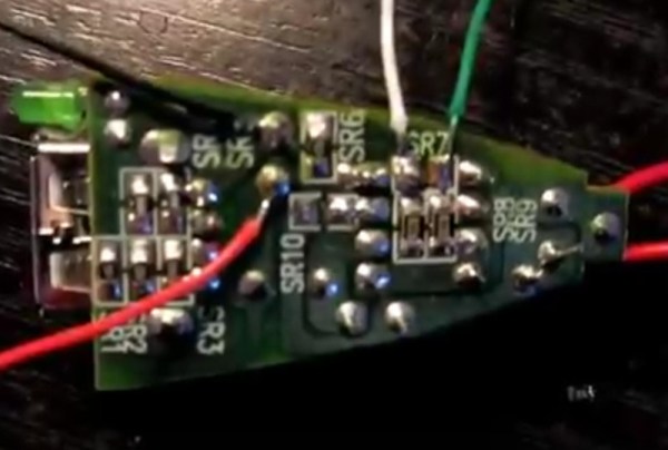
Russian Hacker Multiplies Value Of Boost Converter

We have a love/hate relationship with LiIon batteries. They pack all this power in such a small and light package. But for running 3.3 V devices, they’re cumbersome. They need to be stepped down a little bit when they’re fully charged at 4.2 V, but then they need to be stepped up at the end of their charge around 3.0 V.

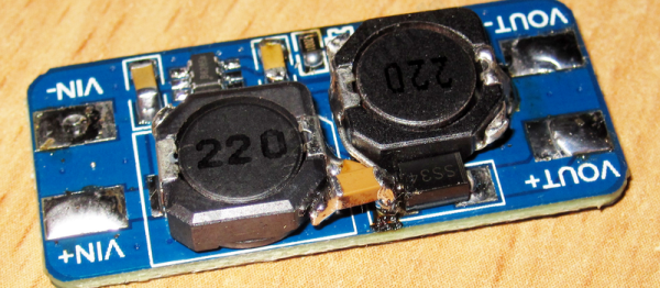
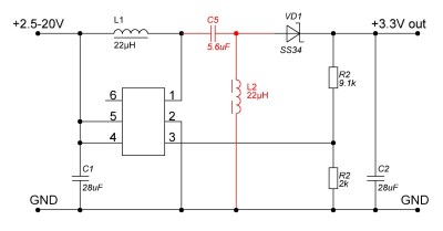
A simple boost or buck converter can’t do both jobs, although you’d be tempted because they can be purchased for peanuts online. So [Kirich] hacked cheap boost converters into the more capable SEPIC topology, which sell for nearly 10x as much. (Google translated version here.) The bottom line? With a little desoldering, a cut trace here and an extra inductor there, and [Kirich] had a very capable circuit that would maintain a constant 3.3 V output when the input swung between 1 V and 5 V.

95aa17If SEPIC power converters are foreign to you, have a read through Maxim’s white paper on the subject. Basically, it’s a boost converter with a capacitor in the middle that lets the output voltage drop below the input voltage. An extra inductor keeps the output side of this capacitor at ground potential (on average).

If you want more detail, [Kirich] doesn’t disappoint. He tested his modifications in multiple configurations on two different models of boost converter. As you’d expect with power circuitry, layout and trace length matters, and [Kirich] took good notes. This is a great read for the frugal hacker, or anyone who’s interested in boost/buck converters.

Speaking of boost/buck circuits, we’ve got some more links for you. This video from Sparkfun’s [Pete Dokter] is worth fifteen minutes, and if you want to get your hands really dirty in the construction of such circuits, this ATtiny-based boost converter circuit is fun to play with.

Thanks [kirillre4] for the great tip!

Programmable DC Backup Power Supply

The uninterruptible power supply was once a standard fixture in the small office/home office as a hedge against losing work when the electrons stop flowing from your AC outlet. Somewhat in decline as computing hardware shifts away from dedicated PCs toward tablets, phones and laptops, the UPS still has a lot of SOHO utility, and off-the-shelf AC units are easy to find. But if your needs run more to keeping the electrons flowing in one direction, then you might want to look at [Kedar Nimbalkar]’s programmable DC backup power system.

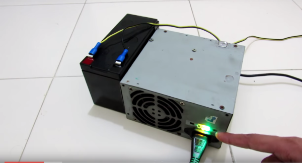
Built inside a recycled ATX power supply case, [Kedar]’s project is heavy on off-the-shelf components, like a laptop power supply for juice, a buck converter to charge the 12 volt sealed lead acid battery, and a boost converter to raise the output to 19.6 volts. An Arduino and an optoisolator are in charge of controlling the charging cycle and switching the UPS from charging the battery to using it when mains voltage drops.

 If you need a DC UPS but would rather skip the battery, you could try running a Raspberry Pi with electrons stashed in a supercapacitor. Or if you’ve got an aging AC UPS, why not try beefing it up with marine batteries?

[Thanks for the tip, Morris]

Microcontroller Adjustment Of A DC To DC Converter

[Hugatry] wanted to replace the adjustment pot on an LM2596 buck converter with a microprocessor-controlled voltage. The regulator IC uses a divider to generate a 1.25V reference from the output. The pot is part of a divider circuit that sets the output voltage. For example, if the divider is 10:1, the controller will keep the output at 1.25V and, therefore, the output voltage will be 12.5V.

[Hugatry’s] strategy was to use a filtered PWM signal from a microcontroller to offset the 1.25V signal. By adding a small voltage to the control point, the output voltage would not need to rise as high as before to maintain the 1.25V reference. For example, adding 0.25V to the reference input would only require 1V, which corresponds to a 10V output.

The video has a nice view of a scope showing the relationship between the PWM duty cycle and the output voltage. Although he didn’t mention it, it struck us that since PWM is proportional to the supply voltage, the voltage on the microcontroller and PWM output stage probably needs to be fixed. That implies you couldn’t use the buck converter to directly power the microcontroller itself. Then again, what kind of microcontroller needs to adjust its own power supply?

Continue reading “Microcontroller Adjustment Of A DC To DC Converter”

Crack Open A USB Car Charger To Make It A Variable DC-DC Converter

[Boolean90] hacked a cheap USB car charger into a variable power supply. His proof of concept is to use this as a variable-speed motor controller. The best part is that nothing is being abused, the regulator inside is still running within manufacturer’s spec.

While we’ve seen similar hacks before, [Boolean90]s video is pretty cool and provides a nice insight into the components used in these cheap devices. Rather than a linear regulator, which would dissipate too much heat the device uses a common jelybean MC34063A (PDF) switching DC-DC converter which costs about 10 cents on eBay (about two dollars for twenty, shipped). Here it’s used to step the car batteries 12 volts down to 5, but can also be used in step-up and inverting configurations.

Like all switching buck converters the MC34063A uses a PWM (pulse width modulated) signal to drive an inductor and capacitor, which effectively form an LC filter. By controlling the pulse width, the output voltage can be regulated. [Afrotechmods] has a great tutorial on the basic principle. The regulation is controlled by feedback resistors. [Boolean90] simply added a variable resistor to allow the output voltage to be controlled.

Neat hack [Boolean90]! Continue reading “Crack Open A USB Car Charger To Make It A Variable DC-DC Converter”

Emergency Power Based On Cordless Drill Batteries

[Don Eduardo] took matters into his own hands after experiencing a days-long power outage at his house. And like most of us have done at least one, he managed to burn his fingers on a regulator in the process. That’s because he prototyped a way to use power tool batteries as an emergency source — basing his circuit on a 7812 linear regulator which got piping hot in no time flat.

His next autodidactic undertaking carried him into the realm of switch-mode buck converters (learn a bit about these if unfamiliar). The device steps down the ~18V output to 12V regulated for devices meant for automotive or marine. We really like see the different solutions he came up with for interfacing with the batteries which have a U-shaped prong with contacts on opposite sides.

The final iteration, which is pictured above, builds a house of cards on top of the buck converter. After regulating down to 12V he feeds the output into a “cigarette-lighter” style inverter to boost back to 110V AC. The hardware is housed inside of a scrapped charger for the batteries, with the appropriate 3-prong socket hanging out the back. We think it’s a nice touch to include LED feedback for the battery level.

We would like to hear your thoughts on this technique. Is there a better way that’s as easy and adaptive (you don’t have to alter the devices you’re powering) as this one?

Continue reading “Emergency Power Based On Cordless Drill Batteries”

A Primer On Buck (and Boost) Converters

We all know that the reason the electrical system uses alternating current is because it’s easy to step the voltage up and down using a transformer, a feature which just isn’t possible with a DC system… or is it? Perhaps you’ve heard of mysterious DC-DC transformers before but never really wanted to look at the wizardry that makes them possible. Now, SparkFun Director of Engineering [Pete Dokter] has a tutorial which explains how these mysterious devices work.

Known as buck converters if they step the input voltage down and boost converters if they step the voltage up, [Pete] explains how these circuits exploit the properties of an inductor to resist changes in current flow. He goes into exquisite detail to explain how components like transistors or MOSFETs are used to switch the current flow to the inductor very rapidly, and just exactly what happens to the magnetic field which makes these devices possible.

The video gives a good amount of background knowledge if you’ve always wanted to understand these devices a little bit better. There are also a few projects floating around that exploit these devices, such as one that uses an AVR microcontroller to perform the switching for a small circuit, or another that uses the interesting properties of these circuits to follow the I-V curve of a solar panel to help charge a bank of batteries. The possibilities are endless!

Continue reading “A Primer On Buck (and Boost) Converters”

Replace Your Project Power Supplies With Recycled Li-Ion Cells And A Switching Regulator

buck-regulator

[Dr. Iguana’s] experience moving from projects powered by disposable Alkaline cells and linear regulators to recycled Lithium Ion cells using the buck regulators seen above might serve as an inspiration to make the transition in your own projects.

The recycled cells he’s talking about are pulled out of larger battery packs. As we’ve seen in the past, dead battery packs for rechargeable tools, laptops, etc., are often plagued by a few bad apples. A small number of dead cells can bork the entire battery even though many perfectly usable cells remain. Once he decided to make the switch it was time to consider power regulation. He first looked at whether to use the cells in parallel or series. Parallel are easier to charge, but boosting the voltage to the desired level ends up costing more. He decided to go with cells in series, which can be regulated with the a less expensive buck converter. In this case he made a board for the RT8289 chip. The drawback of this method requires that you monitor each cell individually during charging to ensure you don’t have the same problem that killed the battery from which you pulled these good cells.