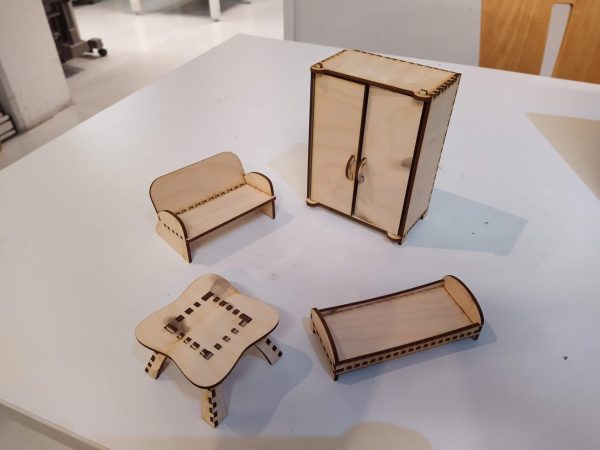
A laser cutter is an incredibly useful tool and they are often found in maker spaces all over. They’re quite good at creating large two-dimensional objects and by cutting multiple flat shapes that connect together you can assemble a three-dimensional object. This is easier when creating something like a box with regular 90-degree angles but quickly becomes quite tricky when you are trying to construct any sort of irregular surface. [Tuomas Lukka] set out to create a dollhouse for his daughter using the laser cutter at his local hackerspace and the idea of creating all the joints manually was discouraging.
The solution that he landed on was writing a python script called Plycutter that can take in an STL file and output a series of DXF files needed by the cutter. It does the hard work of deciding how to cut out all those oddball joints.
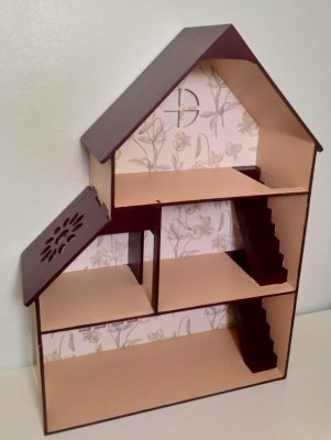
At its core, the system is just a 3D slicer like you’d find for a 3D printer, but not all the slices are horizontal. Things get tricky if more than two pieces meet. [Tuomas] ran into a few issues along the way with floating-point round-off and after a few rewrites, he had a fantastic system that reliably produced great results. The dollhouse was constructed much to his daughter’s delight.
All the code for Plycutter is on GitHub. We’ve seen a similar technique that adds slots, finger-joints, and t-slots to boxes, but Plycutter really offers some unique capabilities.