Baffle The Normies With This Binary Thermometer

We think it’s OK to admit that when someone puts a binary display on a project, it’s just a thinly veiled excuse to get more blinkenlights into the world. That and it’s a way to flex a little on the normies; you’ve gone pretty far down the tech rabbit hole to quickly decipher something like this binary-display thermometer, after all.

Don’t get us wrong, we think those are both perfectly valid reasons for going binary. And all things considered, a binary display for a thermometer like [Clovis Fritzen]’s is much simpler to decode than, say, a clock. Plus, it seems a bit that this build was undertaken at least partially as an exercise in Charlieplexing, which [Clovis] uses to drive the six-bit LED display using only three lines of GPIO from the Digispark ATtiny85 board running the show.

The temperature sensor is a DHT11, whose output is read by the microcontroller before being converted to binary and sent to the six-bit display. The 64-degree range is perfect for displaying the full range of temperatures most of us would consider normal, although we’d find 63°C a touch torrid so maybe there’s a little too much resolution on the upper end of the scale. Then again, switching to Fahrenheit would shift it toward the hypothermia end of the scale, which isn’t helpful. And you can just forget about Kelvin.

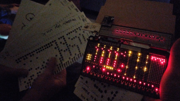
Hackaday supercon badge PCB showing illuminated activity lights after being loaded with a punch card

Supercon Badge Reads A “Punch” Card

This year’s Hackaday Supercon, the first since 2019 thanks to the pandemic, was a very similar affair to those of the past. Almost every hardware-orientated hacker event has its own custom electronic badge, and Supercon was no different. This year’s badge is a simulation platform for a hypothetical 4-bit CPU created by our own [Voja Antonic], and presented a real challenge for some of the attendees who had never touched machine code during their formative years. The challenge set was to come up with the most interesting hack for the badge, so collaborators [Ben Hencke] and [Zach Fredin] set about nailing the ‘expandr’ category of the competition with their optical punched card reader bolt-on.

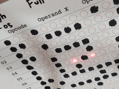
Peripheral connectivity is somewhat limited. The idea was to build a bolt-on board with its own local processing — using a PixelBlaze board [Ben] brought along — to handle all the scanning details. Then, once the program on the card was read, dump the whole thing over to the badge CPU via its serial interface. Without access to theirPrinted paper faux punch card showing read LEDs and an array of set and reset bits of the encoding usual facilities back home, [Ben] and [Zach] obviously had to improvise with whatever they had with them, and whatever could be scrounged off other badges or other hardware lying around.

One big issue was that most people don’t usually carry photodiodes with them, but luckily they remembered that an LED can be used as a photodiode when reverse-biased appropriately. Feeding the signal developed over a one Meg resistance, into a transconductance amplifier courtesy of a donated LM358 there was enough variation for the STM32 ADC to reliably detect the difference between unfilled and filled check-boxes on the filled-in program cards.

The CPU required 12-bit opcodes, which obviously implies 12 photodiodes and 12 LEDs to read each word. The PixelBlaze board does not have this many analog inputs. A simple trick was instead of having discrete inputs, all 12 photodiodes were wired in parallel and fed into a single input amplifier. To differentiate the different bits, the illumination LEDs instead were charlieplexed, thus delivering the individual bits as a sequence of values into the ADC, for subsequent de-serialising. The demonstration video shows that it works, with a program loaded from a card and kicked into operation manually. Such fun!

Punch cards usually have a hole through them and can be read mechanically, and are a great way to configure testers like this interesting vacuum valve tester we covered a short while back.

Continue reading “Supercon Badge Reads A “Punch” Card”

Three pendants that the article is describing, on a drafting mat.They're heart-shaped red PCBs with LEDs all around its perimeter, two CR2032-like batteries in its center.

Heart-Shaped Heartwarming Valentine’s Day Pendant

This is no ordinary heart-shaped PCB pendant project! To us, it’s also symbol representing the striking amount of love that [SaltyPaws] has put into its design and documentation. He tells us that he designed it for the two daughters he is raising, as an electronics and general STEAM introduction – with outstanding educational and aesthetic qualities, giving insights into a wide range of topics while looking . The PCB is mostly through-hole, making for easy soldering and quick return on the effort investment. The project is thought-out beyond the PCB, however – this pendant is designed to be wearable day-to-day, which is why it’s accompanied by a 3D-printed frame, protecting its wearer from sharp PCB edges and through-hole lead ends!

Open-sourcing things is a gift, and today, we are also the recipients. [SaltyPaws] has open-sourced everything involved – PCB files, 3D cover files, firmware, BOM, everything you would need to build your own version. All of this is in a GitHub repository, with detailed sourcing and assembly instructions in the README.md – we couldn’t ask for more! If you have loved ones that would take delight in putting such a pretty pendant together, you have about a week to order the PCBs – after that, Chinese New Year will likely thwart your plans!

Looking for more accessories that double as electronics projects? We’ve covered a wide variety, even when it comes to pendants alone – check out this edge-lit fluorescent acrylic educational Maker Faire accessory, or this circuit sculpture BEAM-inspired bird-imitating one, or this tiny SAMD21-powered pendant with an IPS LCD!

Hackaday Links Column Banner

Hackaday Links: June 14, 2020

You say you want to go to Mars, but the vanishingly thin atmosphere, the toxic and corrosive soil, the bitter cold, the deadly radiation that sleets down constantly, and the long, perilous journey that you probably won’t return from has turned you off a little. Fear not, because there’s still a way for you to get at least part of you to Mars: your intelligence. Curiosity, the Mars rover that’s on the eighth year of its 90-day mission, is completely remote-controlled, and NASA would like to add some self-driving capabilities to it. Which is why they’re asking for human help in classifying thousands of images of the Martian surface. By annotating images and pointing out what looks like soil and what looks like rock, you’ll be training an algorithm that one day might be sent up to the rover. If you’ve got the time, give it a shot — it seems a better use of time than training our eventual AI overlords.

We got a tip this week that ASTM, the international standards organization, has made its collection of standards for testing PPE available to the public. With titles like “Standard Test Method for Resistance of Medical Face Masks to Penetration by Synthetic Blood (Horizontal Projection of Fixed Volume at a Known Velocity)”, it seems like the standards body wants to make sure that that homebrew PPE gets tested properly before being put into service. The timing of this release is fortuitous since this week’s Hack Chat features Hiram Gay and Lex Kravitz, colleagues from the Washington University School of Medicine who will talk about what they did to test a respirator made from a full-face snorkel mask.

There’s little doubt that Lego played a huge part in the development of many engineers, and many of us never really put them away for good. We still pull them out occasionally, for fun or even for work, especially the Technic parts, which make a great prototyping system. But what if you need a Technic piece that you don’t have, or one that never existed in the first place? Easy — design and print your own custom Technic pieces. Lego Part Designer is a web app that breaks Technic parts down into five possible blocks, and lets you combine them as you see fit. We doubt that most FDM printers can deal with the fine tolerances needed for that satisfying Lego fit, but good enough might be all you need to get a design working.

Chances are pretty good that you’ve participated in more than a few video conferencing sessions lately, and if you’re anything like us you’ve found the experience somewhat lacking. The standard UI, with everyone in the conference organized in orderly rows and columns, reminds us of either a police line-up or the opening of The Brady Bunch, neither of which is particularly appealing. The paradigm could use a little rethinking, which is what Laptops in Space aims to do. By putting each participant’s video feed in a virtual laptop and letting them float in space, you’re supposed to have a more organic meeting experience. There’s a tweet with a short clip, or you can try it yourself. We’re not sure how we feel about it yet, but we’re glad someone is at least trying something new in this space.

And finally, if you’re in need of a primer on charlieplexing, or perhaps just need to brush up on the topic, [pileofstuff] has just released a video that might be just what you need. He explains the tri-state logic LED multiplexing method in detail, and even goes into some alternate uses, like using optocouplers to drive higher loads. We like his style — informal, but with a good level of detail that serves as a jumping-off point for further exploration.

Returning Digital Watches To The Analog Age: Enter The Charliewatch

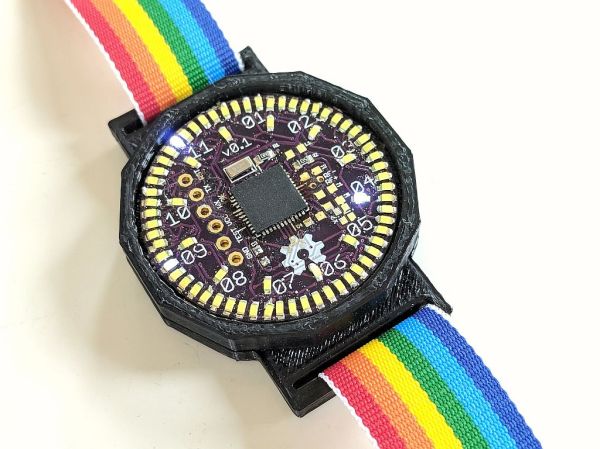
The Charliewatch by [Trammell Hudson] is one of those projects which is beautiful in both design and simplicity. After seeing [Travis Goodspeed]’s GoodWatch21 digital watch project based around a Texas Instruments MSP430-based SoC, [Trammell] decided that it’d be neat if it was more analog. This is accomplished using the CC430F5137IRGZR (a simpler member of the MSP430 family) and a whole bunch of 0603 SMD LEDs which are driven using Charlieplexing.

This time-honored method of using very few I/O pins to control many LEDs makes it possible to control 72 LEDs without dedicating 72 pins. The density makes animations look stunning and the digital nature melts away leaving a distinct analog charm.

A traditional sapphire crystal was sourced from a watchmaker for around 14€ as was the watch band itself. The rest is original work, with multiple iterations of the 3D printed case settling in on a perfect fit of the crystal, PCB, and CR2032 coin cell stackup. The watch band itself hold the components securely in the housing, and timekeeping is handled by a 32.768 kHz clock crystal and the microcontroller’s RTC peripheral.

The LEDs can be seen in both daylight and darkness. The nature of Charlieplexing means that only a few of the LEDs are ever illuminated at the same time, which does wonders for battery life. [Trammell] tells us that it can run for around six months before the coin cell needs replacing.

It’s completely open source, with project files available on the project’s Github page. We hope to see an army of these watches making appearances at all upcoming electronics-oriented events. Just make sure you lay off the caffeine as the process of hand-placing all those LEDs looks daunting.

Tucoplexing: A New Charliplex For Buttons And Switches

Figuring out the maximum number of peripherals which can be sensed or controlled with a minimum number of IOs is a classic optimization trap with a lot of viable solutions. The easiest might be something like an i2c IO expander, which would give you N outputs for 4 wires (SDA, SCL, Power, Ground). IO expanders are easy to interface with and not too expensive, but that ruins the fun. This is Hackaday, not optimal-cost-saving-engineer-aday! Accordingly there are myriad schemes for using high impedance modes, the directionality of diodes, analog RCs, and more to accomplish the same thing with maximum cleverness and minimum part cost. Tucoplexing is the newest variant we’ve seen, proven out by the the prolific [Micah Elizabeth Scott] (AKA [scanlime]) and not the first thing to be named after her cat Tuco.

[Micah’s] original problem was that she had a great 4 port USB switch with a crummy one button interface. Forget replacement; the hacker’s solution was to reverse and reprogram the micro to build a new interface that was easier to relocate on the workbench. Given limited IO the Tucoplex delivers 4 individually controllable LEDs and 4 buttons by mixing together a couple different concepts in a new way.

Up top we have 4 LEDs from a standard 3 wire Charlieplex setup. Instead of the remaining 2 LEDs from the 3 wire ‘plex at the bottom we have a two button Charlieplex pair plus two bonus buttons on an RC circuit. Given the scary analog circuit the scan method is pleasingly simple. By driving the R and T lines quickly the micro can check if there is a short, indicating a pressed switch. Once that’s established it can run the same scan again, this time pausing to let the cap charge before sensing. After releasing the line if there is no charge then the cap must have been shorted, meaning that switch was pressed. Else it must be the other non-cap switch. Check out the repo for hardware and firmware sources.

Last time we talked about a similar topic a bunch of readers jumped in to tell us about their favorite ways to add more devices to limited IOs. If you have more clever solutions to this problem, leave them below! If you want to see the Twitter thread with older schematics and naming of Tucoplexing look after the break.

Continue reading “Tucoplexing: A New Charliplex For Buttons And Switches”

Get Twelve Charlieplexed PWM Outputs From An ATtiny85

Most of us are aware that charlieplexing can drive a large number of LEDs from a relatively small number of I/O pins, but [David Johnson-Davies] demonstrates adding another dimension to that method to create individually controlled PWM outputs as well. His ATtiny85 has twelve LEDs, each with individually-set brightness levels, and uses only four of the five I/O pins on the device.

Each LED can be assigned a brightness between 0 (fully off) and 63 (fully on). The PWM is done by using one of the timers in the ATtiny85 to generate a periodic interrupt, and the ISR for the interrupt takes care of setting the necessary ratios of on and off times for each charlieplexed output. The result? Twelve flicker-free LEDs with individually addressable brightness levels, using an 8-pin microcontroller and just a few passive components on a tiny breadboard. There’s even one I/O pin left on the ATtiny85, for accepting commands or reading a sensor.

[David] really wrings a lot out of the ATtiny series of microcontrollers with his compact projects, like his Tiny Function Generator (which recently got an update.) He also demonstrated that while charlieplexing is usually used with LEDs, charlieplexing can be used with switches just as easily.