Camera Light Meter

Upgrading An Old Camera With A New Light Meter

[Marc] has an old Voigtländer Vito CLR film camera. The camera originally came with an analog light meter built-in. The meter consisted of a type of solar panel hooked up to a coil and a needle. As more light reached the solar panel, the coil became energized more and more, which moved the needle farther and farther. It was a simple way of doing things, but it has a down side. The photo panels stop working over time. That’s why [Marc] decided to build a custom light meter using newer technology.

[Marc] had to work within the confines of the tiny space inside of the camera. He chose to use a LM3914 bar display driver IC as the primary component. This chip can sense an input voltage against a reference voltage and then display the result by illuminating a single LED from a row of ten LEDs.

[Marc] used a photo cell from an old calculator to detect the ambient light. This acts as a current source, but he needed a voltage source. He designed a transimpedence amplifier into his circuit to convert the current into a voltage. The circuit is powered with two 3V coil cell batteries, regulated to 5V. The 5V acts as his reference voltage for the display driver. With that in mind, [Marc] had to amplify this signal further.

It didn’t end there, though. [Marc] discovered that when sampling natural light, the system worked as intended. When he sampled light from incandescent light bulbs, he did not get the expected output. This turned out to be caused by the fact that incandescent lights flicker at a rate of 50/60 Hz. His sensor was picking this up and the sinusoidal output was causing problems in his circuit. He remedied this by adding two filtering capacitors.

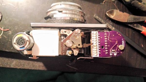
The whole circuit fits on a tiny PCB that slides right into position where the original light meter used to be. It’s impressive how perfectly it fits considering everything that is happening in this circuit.

[Thanks Mojay]

Etching PCBs With A 3D Printer

There are dozens of circuit board printers out there that lay down traces of conductive ink and ask you to glue down components to a fragile circuit board. This is a far cry from the old way of making PCBs, but these printers are going gangbusters, cashing in on the recent popularity of hardware startups and rapid prototyping.

People who think deeply about a problem are few and far between, but lucky for us [Arvid] is one of them. He’s come up with a way of creating PCBs with any 3D printer and steel rod. The results are better than anything you could make with a circuit board printer, and the technique is very, very cheap.

[Arvid] is using the traditional method of etching away copper, just some ferric chloride and a bit of time. How he’s masking the copper that shouldn’t be etched away is a unique process we haven’t seen before. He’s simply covering a piece of copper clad board with permanent marker, and scribing the parts he wants to be etched with a sharp steel rod attached to a 3D printer.

The G code for the printer was generated by FlatCAM, a piece of software made specifically for cutting PCBs with a mill. [Arvid]’s technique works so well that spindles and mills aren’t needed; only a sufficiently sharp instrument to scrape away permanent marker.

Thanks [Hassi] for sending this one in.

Remote Tester

A Simple Circuit For Testing Infrared Remote Controls

Every now and then a remote control acts up. Maybe you are trying to change the channel on your television and it’s just not working. A quick way to determine if the remote control is still working is by using a cell phone camera to try to see if the IR LED is still lighting up. That can work sometimes but not always. [Rui] had this problem and he decided to build his own circuit to make it easier to tell if a remote control was having problems.

The circuit uses a Vishay V34836 infrared receiver to pick up the invisible signals that are sent from a remote control. A Microchip 12F683 processes the data and has two main output modes. If the remote control is receiving data continuously, then a green LED lights up to indicate that the remote is functioning properly. If some data is received but not in a continuous stream, then a yellow LED lights up instead. This indicates that the batteries on the remote need to be replaced.

The circuit also includes a red LED as a power indicator as well as RS232 output of the actual received data. The PCB was cut using a milling machine. It’s glued to the top of a dual AAA battery holder, which provides plenty of current to run the circuit.

Woodcut Stamps And Conductive Ink

circuit

Even though it’s been a while since the Rome Maker Faire, we’re still getting some tips from the trenches of Europe’s largest gathering of makers. One of these is a 30-minute experiment from [Luong]. He wondered if it would be possible to create SMD circuit boards by using a 3D printer to fabricate a stamp for conductive ink.

[Luong] told this idea  to a few folks around the faire, and the idea eventually wound up in the laps of the guys from TechLab. the Chieri, Italy hackerspace. They suggested cutting a wooden stamp using a laser cutter and within 30 minutes of the idea’s inception a completed stamp for an Atari Punk Console PCB was in [Luong]’s hands.

As an experiment, the idea was a tremendous success. As a tool, the stamp didn’t perform as well as hoped; the traces didn’t transfer properly, and there’s no way this wooden laser cut stamp could ever create usable PCBs.

That being said, we’re thinking [Luong] is on the right track here with printed PCBs. One of the holy grails of home fabrication is the creation of printed circuit boards, and even a partial success is too big to ignore.

This idea for CNC-created PCB stamps might work with a different material – linoleum or other rubber stamp material, or even a CNC milled aluminum plate. If you have any ideas on how to use this technique for PCB creation, leave a note in the comments, or better yet, try it out for yourself.

Understanding Op-amps From Simple To Hard

[Tim] wanted to help out a ECE student struggling with some Op-Amp problems. He put together a video which does a good job of explaining what an Op-Amp does, then tackles each of the questions one at a time.

His analogy is illustrated in this image. There’s an operator using a crane to lift a crate. He is watching a ‘radio man’ in a window of the building to know how high it should be lifted. These roles are translated to the function of an Op-Amp in a way that makes understanding the common parts quite easy. The crane is the Op-Amp and the floor to which it is trying to lift the crate is the input pin. The current height of the crate is the output signal. The radio man is the feedback resistor which is trying to get the desired height and current height to equal each other. Watch the video after the break and all becomes clear.

After this analogy is explained [Tim] tackles the actual homework problems. He’s going through everything pretty quickly, and doesn’t actually give the answers. What he does is show how this — like most circuit solving problems — depends on how you group the components in order to simplify the questions. Grab a pen and paper and put on your electron theory hats to see if you can solve the questions for yourselves.

Continue reading “Understanding Op-amps From Simple To Hard”

Conductive Ink Circuit Experiments

This glowing LED is proof that the experiments [Nvermeer] is doing with conductive ink are working. We’re filing this one as a chemistry hack because  you need to hit the lab ahead of time in order to get the conductivity necessary for success. He reports that this technique uses a copper powder suspended in an epoxy intended for spray painting. Before mixing the two he etched the powder in ammonium persulfate, then washed it in deionized water which made it a much better conductor.

We gather that the ink was applied with the brush seen in the photo. But since this uses that spray paint friendly solution to host the copper powder we wonder about stenciling with something like masking tape in order to spray the circuit paths onto the substrate.

There’s not too much info up yet, but [Nvermeer] does link to one of our other favorite conductive ink projects.

Browser-based Circuit Simulator Boasts A Mountain Of Features

CircuitLab is an electronics simulator which you can run in a browser. Above you can see one of the example circuits provided to help show the power of the application. You can build your schematic (perhaps you want to try [Jeri’s] psu shut-off timer?) in the editor mode, then switch over to the simulator to get data back from the components. In that mode, your cursor becomes a probe, and clicking on different parts of the circuit will return the calculated input and output voltages for that component. But wait, there’s more. It’s got time and frequency simulation in addition to the voltage simulator. This lets you look at waveforms fed through analog filters, or timing data like in the 555 timer circuit above.

Where does this fantastic tool come from? [Humberto Evans] and [Mike Robbins], the guys behind NerdKits developed this site. We’ve seen a lot of their hacks around here, like milling solenoids and making them play a xylophone. Check out the CircuitLab quick start video they put together after the break. Continue reading “Browser-based Circuit Simulator Boasts A Mountain Of Features”