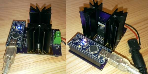
At first glance, [RobBest]’s constant current source looks old school. The box is somewhat old-fashioned, featuring switches and binding posts. Most importantly, there’s a large analog meter dominating the front panel. Then you notice the OLED display, and you know something’s up.
The device can source or sink a constant current. In addition, it features a timer that calculates milliamp-hours and automatically turns off when not in use. The brain is a PIC 16F1765, which controls the screen, the buttons, and a few relays. While that might seem an odd choice for the processor, it is actually smart. The device has both a DAC and an ADC, plus an internal op amp. The analog output and a single pass transistor control the current flow, while the two relays flip it between a source and a sink.
Without that op amp, the DAC can’t produce much current. However, by passing it through the onboard amplifier, the output can drive about 100 mA, which is sufficient for this project.
This is a classic circuit, but the addition of a CPU and a display gives it capabilities that would have been very difficult to build back in the day. Want to dive into the theory behind constant current sources? Or just the practical use of a voltage regulator to make one?

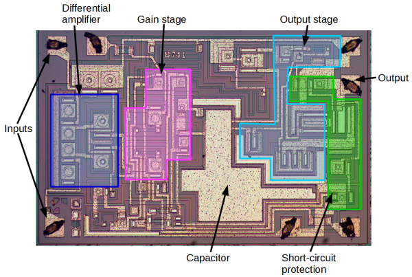
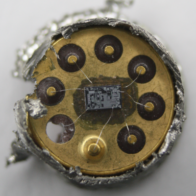 Rather than risk the boiling acid method commonly used to decap epoxy-potted ICs, [Ken] wisely chose a TO-99 can format to attack with a hacksaw. With the die laid bare for his microscope, he was able to locate all the major components and show how each is implemented in silicon. Particularly fascinating is the difference between the construction of NPN and PNP transistors, and the concept of “current mirrors” as constant current sources. And he even whipped up a handy interactive chip viewer – click on something in the die image and find out which component it is on the 741 schematic. Very nice.