Making Instagram With An Old CRT

If you’re not familiar with Instagram, it’s a mobile app that takes pictures, applies low-fi ‘lomographic’ digital filters, and shares them on the Internet. For reasons we can’t comprehend, Instagram has been wildly successful as of late and was recently purchased by Facebook for a Billion dollars. [Martin Ström] figured he could do something much cooler than applying digital filters to a cell phone picture, so he built InstaCRT, an app that turns your pictures into grainy CRT images and satiates the geek and hipster in everyone.

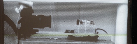
From [Martin]’s project page, InstaCRT uses a small black and white CRT from an old camcorder and a Canon 7D to apply real-world analog filters to all the uploaded pictures. Once the pictures are uploaded to the MacBook Pro server, they’re displayed on the CRT and a picture is taken with the 7D. Once an Android/iOS device sends a picture to the server, it’s displayed on the CRT, the 7D snaps a picture, and the resulting ‘filtered’ picture is sent back to the mobile device.

While we’re sure a few Hackaday commentors are going to ask ‘why’, it’s still a very cool build that is the first real world digital camera filter we’ve seen. You can check out the video demo of InstaCRT after the break.

Continue reading “Making Instagram With An Old CRT”

You’ll Throw Your Back Out Playing This Analog TV Synth

de-rastra

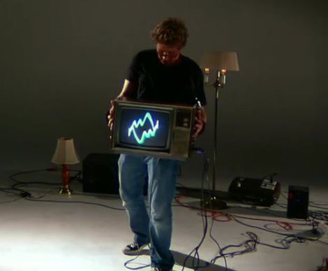
While CRT televisions fall to the wayside as more people adopt flat-panel TVs, the abundance of unused sets gives hacker/artist [Kyle Evans] an unlimited number of analog canvases on which to project his vision. He recently wrote in to share his latest creation which he dubs “de/Rastra”.

The “CRT Performance Interface” as he calls it, is an old analog television which he hacked to display signals created by moving the TV around. Fitted with an array of force sensors, accelerometers, and switches, the display is dynamically generated by the movements of whomever happens to be holding the set.

Signals are sent wirelessly from his sensor array to an Atmel 328 microcontroller with the help of a pair of XBee radios, where they are analyzed and used to generate a series of audio streams. The signals are fed into a 400W amplifier before being inserted into the CRT’s yoke, and subsequently displayed on the screen.

We’re sure [Kyle] is probably trying to express a complex metaphor about man’s futile attempts to impose his control over technology with his project, but we think it simply looks cool.

Check out [Kyle’s] work for yourself in the video below and give us your take in the comments.

Continue reading “You’ll Throw Your Back Out Playing This Analog TV Synth”

CRT Vector Graphics Arcade Game Built From An FPGA Board

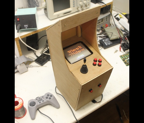
[Sprite_TM] wanted to challenge his VHDL skills, and there’s no more satisfying way of doing this than making something that will be playable when you’re done. He decided to try his hand at creating a vector-based CRT arcade. The distinction here is that vector-based games take control of the magnetic ring that guides the electron path toward the screen. This technique allows point-to-point graphic generation rather than the pixel-based scanning that CRT televisions use.

He had a small color CRT on hand and decided to grab a VHDL version of asteroids from the Internet to see if he could get it to work. But upon further inspection of the source he found that it had a chunk of code which rasterized the vectors for use with a scanning monitor. After removing that chunk, and giving it a spin he had enough confidence that he knew what he was doing to start implementing his own game. The choice of what title really came down to the hardware the original arcade cabinets used. He was not interested in implementing a soft-process for the math chips used in games like Star Wars and Tempest. In the end he got a version of Black Widow up and running, and even built a miniature cabinet for the thing. Check out some of the gameplay in the clip after the break.

Continue reading “CRT Vector Graphics Arcade Game Built From An FPGA Board”

Installing Military Hardware In A Home Flight Simulator

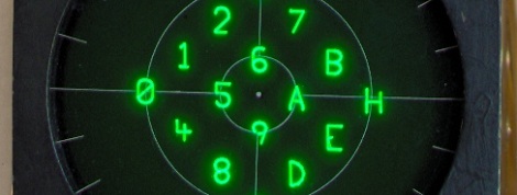
The cockpit of an F-16 Fighting Falcon features a small 3-inch display that monitors and tracks hostile aircraft and missiles, friendlies, and the current target. This Radar Warning Receiver is vitally important to pilots in combat, so [Mike] decided to add one to his homebuilt F-16 simulator that runs Falcon 4.0.

The RWR displays threats as symbols that are usually generated by tens of thousands of dollars worth of military hardware. [Mike] figured a $7 PIC microcontroller would work just as well and set about designing vector graphics that would fit on a single chip.

[Mike] had the graphics displaying correctly on an oscilloscope, but that’s a far cry from the from the surplus RWR display he picked up. Although the display is a simple CRT, the original designers of the radar warning receiver thought it necessary to put the deflection amplifiers in another part of the airplane. After building a pair of 30 Watt amplifiers, [Mike] could finally display more than a single dot on the display.

After all was said and done, [Mike] has a wonderful radar warning display that fits into his F-16 cockpit perfectly. While it’s not quite a 737 in a garage, we’ve got to respect someone who takes surplus avionics and makes them work. Check out [Mike]’s display in action after the break.

Continue reading “Installing Military Hardware In A Home Flight Simulator”

Glove-based Touch Screen From A CRT Monitor

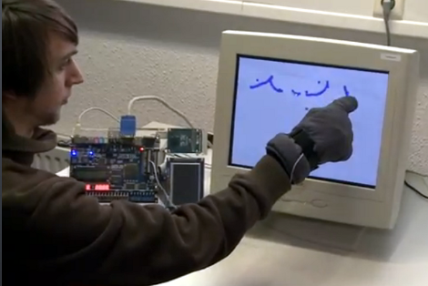
Here’s a bulky old CRT monitor used as a touch-screen without any alterations. It doesn’t use an overlay, but instead detects position using phototransistors in the fingertips of a glove.

Most LCD-based touch screens use some type overlay, like these resistive sensors. But cathode-ray-tube monitors function in a fundamentally different way from LCD screens, using an electron gun and ring of magnets to direct a beam across the screen. The inside of the screen is coated with phosphors which glow when excited by electrons. This project harness that property, using a photo transistor in both the pointer and middle finger of the glove. An FPGA drives the monitor and reads from the sensors. It can extrapolate the position of the phototransistors on the display based on the passing electron beam, and use that as cursor data.

Check out the video after the break to see this in action. It’s fairy accurate, but we’re sure the system can be tightened up a bit from this first prototype. There developers also mention that the system has a bit of trouble with darker shades.

Continue reading “Glove-based Touch Screen From A CRT Monitor”

Retro Hardware Mash-up Spouts Archaic Geekery

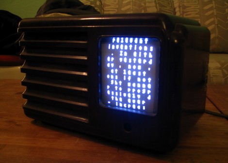
This delightful little box is something only a hacker could love. It uses some second-hand hardware to display random sayings attributed to [Buckminster Fuller]. The image above doesn’t do the display justice. There are other photos which show very crisp lettering which is easier to read.

[Autuin] always keeps his eyes open for cool gear at the end of its consumer life. The screen for this project is a CRT from a Coleman TV lantern (you know, for camping… bah!). It finds a home in the chassis of an old non-functional radio he had picked up a few years earlier. With those parts in hand the real adventure started: getting an Arduino to read in quotes and generate a TV out signal to display them.

We love the SD card holder which he fashioned from a card-edge connector he grabbed at the local electronics store. From there he scoured the Internet for help on where to patch into the TV signal. Once the right trace was discovered the Arduino TV out library does the heavy lifting.

A Clock Made Out Of Some Very Weird Tubes

If you’re like [Richard], you’ve got a few really rare components lying around. Maybe it’s a very weird micro or a really tiny CRT, but eventually you’ve got to build something with these parts. When [Richard] decided to put some ITS1A neon display tubes to use, he fell back to the old standby – a really awesome clock.

Unlike the lowly Nixie tube, the ITS1A tube is weird. It’s a neon seven-segment display that can be controlled directly from the pins of a microcontroller. It does this with the help of seven tiny thyratrons in each segment. Even though this tube has neon, the display isn’t the familiar neon orange-red. The tube emits a lovely green with the help of a phosphor coating.

With a single digit already incorporated into [Richard]’s clock, he needed four indicators for the hours and minutes. After a failed experiment with a crazy 4-color, 16-pixel Melz ITM2-M display, he moved on to a simpler MTX90 thyratron indicator.

Using the same control scheme as his earlier numitron clock, Richard had a PCB made and wired everything up. The seven-segment tube indicates the value, and the indicator tubes indicates the position of the digit in the XX:XX standard. A very cool  build with parts you don’t see coming around often.