I usually see retro-gaming projects using tiny screens with a fair number of pixels (64×64) but what I really like is the look of making every pixel count. With this in mind I built 1-Pixel Pac-Man, the classic coin-op experience but with characters that consist of just one pixel. Playing a throw-back like this wouldn’t be the same without some vintage controls so I picked up an Atari joystick, patched it into a microcontroller, and started coding. Check it out:
Smartmatrix Bundle


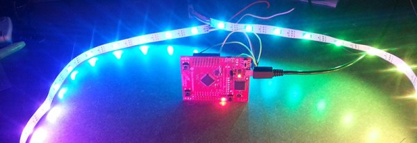
This piece of hardware made the project build really easy: the Smartmatrix. [Louis Beaudioin] developed the Smartmatrix and it’s been in the Hackaday Store for a while now. The display module itself is a commodity item that is used in LED billboards. There are shrouded headers on the back of the panels, to the left and right sides, which allow them to be daisy chained. The Smartmatrix PCB plugs into one of these shields, provides a soldering footprint for the Teensy 3.1 which drives the display, and gives you the wiring to connect screw terminals from the PCB to the power terminals on the module. Why the need for beefy power jumpers? At full white the thing can draw about 3.5A — don’t worry there’s a power supply included in the bundle.
Also integral to making this look good is the diffuser panel which is frosted acrylic. The Smartmatrix is designed to be housed in a shadowbox frame; it even includes a frame backer board with a cut-out for the Teensy 3.1 so it can be programmed without opening the thing up. I like looking at the guts so I’m leaving my free floating until I come up with an interesting way to mount everything as one unit.
Programming Pac-Man from the Ground Up
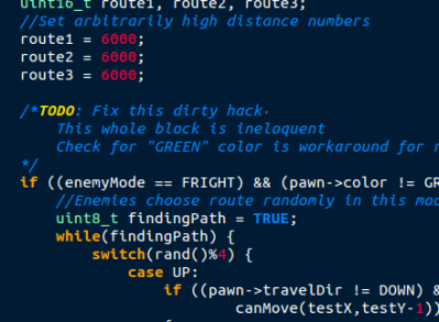
If you haven’t looked into it before, the ghost AI and gameplay details for Pac-Man are absolutely brilliant. [Toru Iwatani] did a masterful job with the original, and you should take a look at all of the analysis that has been done over the years. The best collection I could find was the Pac-Man Dossier and I based most of my code on the rules described there.
Basically the ghosts have two modes, chase and scatter. The modes set the enemy targets differently; to points at the four corners of the board in scatter, and to points relative to the player in chase. The relative part is key; only the red enemy actually chases you. Another one of them looks at the red enemy’s distance and angle, and targets the reflection of that vector. Really easy, really clever, and results in enemy behavior that’s believable. It isn’t just the enemy movement, little touches like a speed penalty (1/60 of a second) for each dot the player gobbles up means the enemies can catch up if you continuously eat, but you can escape by taking the path already-eaten.
Library, DMA, and Extra Hardware


The hardware and software running the Smartmatrix made the display portions of the project really simple. First off, the Teensy 3.1 is fast, running at 96MHz in this case. Second, it has Direct Memory Access (DMA) which [Louis] used in the Smartmatrix library. This means that driving the display takes almost no CPU time at all, leaving the rest for your own use. This example of a game is under-utilizing this power… it’s totally capable of full-motion video and calculating amazing visualizations on the fly.
The PCB hosting the Teensy 3.1 breaks out several pins to one side. I’m not sure what I’ll add in the future so I actually used the extra surface-mount IO pins on the bottom of the Teensy to connect the Atari joystick (which is simply a set of switches). The are enough pads for two joysticks so I used pin sockets to interface the Teensy to the PCB so that I can get to it again later.
The kit also includes an IR receiver and remote, and also a microSD card to loading animations (there’s an SD socket on the PCB). The bundle in the Hackaday Store is a kit you solder yourself, but [Louis’] company, Pixelmatix, has a Kickstarter running for fully-assembled versions that come with a black remote and sound-visualization hardware.
Future Improvements
The game is fully working, but there are a few key things that I really want to add. The Teensy 3.1 has a single DAC pin available. I’m fairly certain the original coin-op game had mono audio. It should be possible to reproduce the sound quite accurately with this board. That would really make the project pop.
There are also a bunch of touch-ups that need to happen. I’d like to add an animation when the player is eaten by an enemy, and a countdown before the level restarts. The score, shown in binary on the right column, should be scrolled out in decimal when the game ends, and what’s a coin-op recreation without a high-score screen?