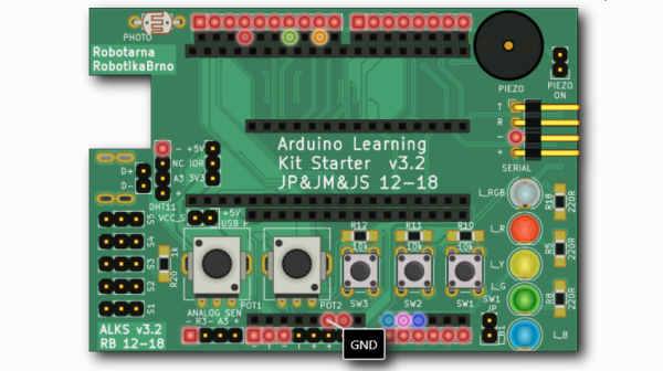
Hackaday Prize Entry: FabDoc Is Version Control For Project Images

FabDoc is an interesting concept that attempts to tackle a problem many of us didn’t realize we had. There are plenty of version control systems for software, but many projects also have a hardware element or assembly process. Those physical elements need to be documented, but that process does not easily fit the tools that make software development and collaboration easier. [Kevin Cheng] sums FabDoc up as “a system to capture time-lapse pictures as pre-commits.”

With FabDoc a camera automatically records the physical development process, allowing the developer to focus on work and review later. The images from the camera are treated as pre-commits. Upon review, the developer selects relevant key images (ignoring dead ends or false starts) and commits them. It’s a version control and commit system for the physical part of the development process. The goal is to remove the burden of stopping the work process in order to take pictures, automatically record the development process and attach it to a specific project, and allow easy management of which images to commit.

The current system uses a Raspberry Pi Zero with a camera mounted on safety glasses, and some support software. Some thought has certainly gone into making the system as easy to use and manage as possible; after setting up a repository, scanning a QR code takes care of telling the system what to do and where to put it. The goal is to make FabDoc fast and easy to use so that it can simply work unattended.

We saw a visual twist on version control some time ago with a visual diff for PCBs, which was a great idea to represent changes between PCB designs visually, diff-style. It’s always exciting to see someone take a shot at improving processes that are easy to take for granted.

A Tool For KiCad Board Renderings

If you’re producing documentation for a PCB project, you might as well make the board renders look good. But then, that’s a lot of work and you’re not an artist. Enter [Jan]’s new tool that takes KiCad board files, replaces each footprint with (custom) graphics, and provides a nice SVG representation, ready for labelling. If you like the output of a Fritzing layout, but have higher expectations of the PCB tool, this is just the ticket.

We all love [pighixx]’s pinout diagrams. Here’s his take on the Arduino Uno, for instance. It turns out that he does these largely by hand. That’s art for ya.

Sparkfun has taken a stab at replicating the graphical style for the pin labels, but then they toss in a photo of the real item. [Jan]’s graphic PCB generator fills in the last step toward almost putting [pighixx] out of a job. Get the code for yourself on GitHub.