Sprucing Up A Bell & Howell Model 34 Oscilloscope

We’ll admit it, in an era when you can get a four channel digital storage oscilloscope with protocol decoding for a few hundred bucks, it can be hard not to see the appeal of analog CRT scopes from decades past. Sure they’re heavy, harder to use, and less capable, but they just look so cool. Who could say no to having one of these classic pieces of gear on their bench?

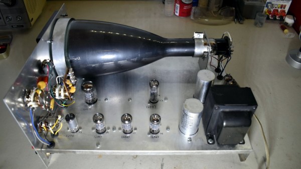
[Cody Nybo] certainly couldn’t. Despite the fact that he already has a digital scope, he couldn’t pass up the chance to add a Bell & Howell Schools Model 34 from circa 1973 to his collection. It needed a bit of TLC before it could be brought back into service, but now it’s all fixed up and ready to put in some work. Not bad for a piece of gear with nearly a half-century on the clock.

The restoration of the Model 34 was aided by the fact that [Cody] got the original manual and schematics for the scope in the deal, which he was kind enough to scan and upload for the rest of the class to enjoy. Those of you who have worked on older electronics can already guess where the scope needed the most love: all the capacitors needed to be swapped out for fresh ones. He also found a few resistors that were out of spec, and the occasional bad solder joint here and there.

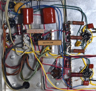
Even if you’re not looking to repair your own middle-aged oscilloscope, his pictures of the inside of Model 34 are fascinating. The scope was sold as a kit, so the construction is surprisingly simple and almost entirely point-to-point. Of course, there’s something of a trade-off at work: [Cody] says it won’t display much more than 2.5 MHz before things start getting wonky. But then again, that’s a more than reasonable frequency ceiling for audio work and most hobbyist projects.

Oscilloscopes have come a long way since the days when they had to draw out their readings on a piece of paper. While newer devices have all but buried the classic analog scope, a beauty like this would still have a place of honor in our lab.

Rebuilding An Amiga 500 PSU

One of the challenges of keeping a vintage computer up and running is the limited availability of spare parts. While not everything has hit dire levels of availability (not yet, anyway), it goes without saying that getting a replacement part for a 30+ year old computer is a bit harder than hitting up the local electronics store. So the ability to rebuild original hardware with modern components is an excellent skill to cultivate for anyone looking to keep these pieces of computing history alive in the 21st century.
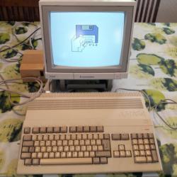
This is in ample evidence over at [Inkoo Vintage Computing], where repairs and upgrades to vintage computers are performed with a nearly religious veneration. Case in point: this detailed blog post about rebuilding a dead Amiga 500 power supply. After receiving the machine as a donation, it was decided to attempt to diagnose and repair the PSU rather than replace it with a newly manufactured one; as much for the challenge as keeping the contemporary hardware in working order.

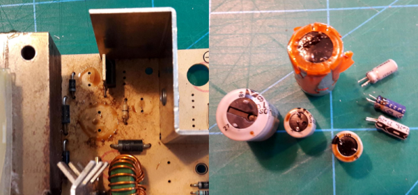
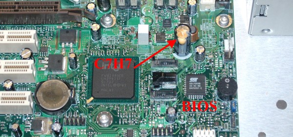
What was found upon opening the PSU probably won’t come as a huge surprise to the average Hackaday reader: bad electrolytic capacitors. But these things weren’t just bulged, a few had blown and splattered electrolyte all over the PCB. After removing the bad caps, the board was thoroughly inspected and cleaned with isopropyl alcohol.

[Inkoo Vintage Computing] explains that there’s some variations in capacitor values between different revisions of the Amiga PSU, so it’s best to match what your own hardware had rather than just trying to look it up online. These capacitors in particular were so old and badly damaged that even reading the values off of them was tricky, but in the end, matching parts were ordered and installed. A new fuse was put in, and upon powering up the recapped PSU, the voltages at the connector were checked to be within spec before being plugged into the Amiga itself.

As a test, the Amiga 500 was loaded up with some demos to really get the system load up. After an hour, the PSU’s transformer was up to 78°C and the capacitors topped out at 60°C. As these parts are rated for 100°C (up from 85°C for the original parts), everything seemed to be within tolerances and the PSU was deemed safe for extended use.

This sort of repair isn’t exactly rare with hardware this old, and we’ve seen similar work done on a vintage Apple power supply in the past. If you’re less concerned with historical accuracy, [Inkoo Vintage Computing] has also shown off adapting an ATX PSU for use with the Amiga.

Replace Old Electrolytics? Not So Fast… Maybe

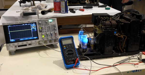
[CuriousMarc] was restoring an old Model 19 TeleType. The design for these dates back to the 1930s, and they are built like tanks (well, except for the ones built during the war with parts using cheaper metals like zinc). Along the way, he restored a hefty tube-based power supply that had two very large electrolytic capacitors. These dated from the 1950s, and common wisdom says you should always replace old electrolytics because they don’t age well and could damage the assembly if powered up. [Marc] didn’t agree with common wisdom, and he made a video to defend his assertion which you can see below.

If you look at the construction of electrolytic capacitors, one plate of the capacitor is actually a thin layer that is formed electrically. In some cases, a capacitor with this plate is damaged can be reformed either by deliberate application of a constant current or possibly even just in normal operation.

Continue reading “Replace Old Electrolytics? Not So Fast… Maybe”

Sodium bicarbonage diode steering circuit

Soda Bicarb Diode Steering Circuit For 7-Segment Display

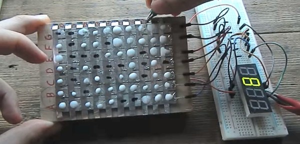
[Hales] has been on a mission for a while to make his own diodes and put them to use and now he’s succeeded with diodes made of sodium bicarbonate and water, aluminum tape and soldered copper. By combining 49 of them he’s put together a soda bicarb diode steering circuit for a 7-segment display capable of showing the digits 0 to 9.

He takes the idea for his diode from electrolytic capacitors. A simple DIY electrolytic capacitor has an aluminum sheet immersed in a liquid electrolyte. The aluminum and the conductive electrolyte are the two capacitor plates. The dielectric is an aluminum oxide layer that forms on the aluminum when the correct polarity is applied, preventing current flow. But if you reverse polarity, that oxide layer breaks down and current flows. To [Hales] this sounded like it could also act as a diode and so he went to work doing plenty of experiments and refinements until he was confident he had something that worked fairly well.

In the end he came up with a diode that starts with a copper base covered in solder to protect the copper from his sodium bicarbonate and water electrolyte. A piece of aluminum tape goes on top of that but is electrically insulated from it. Then the electrolyte is dabbed on such that it’s partly on the solder and partly on the aluminum tape. The oxide forms between the electrolyte and the aluminum, providing the diode’s junction. Connections are made to the soldered copper and to the aluminum.

To truly try it out he put together a steering circuit for a seven segment display. For that he made a matrix of his diodes. The matrix has seven columns, one for each segment on the display. Then there are ten rows, one for each digit from 0 to 9. The number 1, for example, needs only two segments to light up, and so for the row representing 1, there are only two diodes, i.e. two dabs of electrolyte where the rows overlap the columns for the desired segments. The columns are permanently wired to their segments so the final connection need only be made by energizing the appropriate row of diodes. You can see [Hales] demonstrating this in the video below the break.

Continue reading “Soda Bicarb Diode Steering Circuit For 7-Segment Display”

Repairing 14 Tektronix TLA5202 Logic Analyzers

[Matthew D’Asaro] was recently entrusted with an entire classroom fleet of fourteen broken Tektronix TLA5202 logic analyzers — a pile of equipment that once was worth hundreds of thousands of dollars. His task: Fixing them. He fixed them all, and on the way documented a number of common failure points in these old but still great devices.

Continue reading “Repairing 14 Tektronix TLA5202 Logic Analyzers”

History Of The Capacitor – The Modern Era

The pioneering years in the history of capacitors was a time when capacitors were used primarily for gaining an early understanding of electricity, predating the discovery even of the electron. It was also a time for doing parlor demonstrations, such as having a line of people holding hands and discharging a capacitor through them. The modern era of capacitors begins in the late 1800s with the dawning of the age of the practical application of electricity, requiring reliable capacitors with specific properties.

Leyden Jars

Marconi with transmitting apparatus
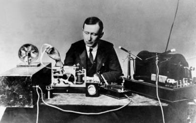
Marconi with transmitting apparatus, Published on LIFE [Public domain], via Wikimedia Commons
One such practical use was in Marconi’s wireless spark-gap transmitters starting just before 1900 and into the first and second decade. The transmitters built up a high voltage for discharging across a spark gap and so used porcelain capacitors to withstand that voltage. High frequency was also required. These were basically Leyden jars and to get the required capacitances took a lot of space.

Mica

In 1909, William Dubilier invented smaller mica capacitors which were then used on the receiving side for the resonant circuits in wireless hardware.

Early mica capacitors were basically layers of mica and copper foils clamped together as what were called “clamped mica capacitors”. These capacitors weren’t very reliable though. Being just mica sheets pressed against metal foils, there were air gaps between the mica and foils. Those gap allowed for oxidation and corrosion, and meant that the distance between plates was subject to change, altering the capacitance.

In the 1920s silver mica capacitors were developed, ones where the mica is coated on both sides with the metal, eliminating the air gaps. With a thin metal coating instead of thicker foils, the capacitors could also be made smaller. These were very reliable. Of course we didn’t stop there. The modern era of capacitors has been marked by one breakthrough after another for a fascinating story. Let’s take a look.

Continue reading “History Of The Capacitor – The Modern Era”

Electrolytic Capacitor Repair

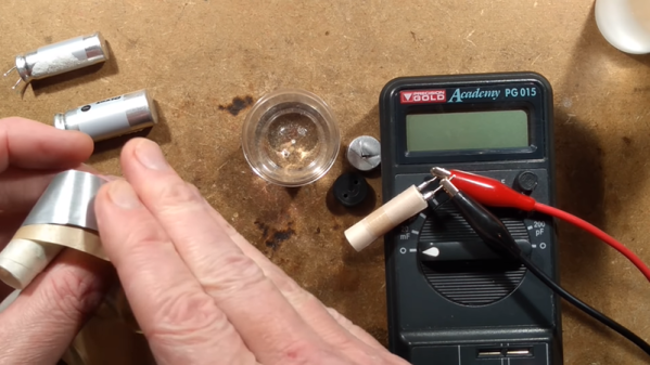
If you’ve ever worked on old gear, you probably know that electrolytic capacitors are prone to failure. [Dexter] undertook a repair of some four-decade-old capacitors in a power supply. He didn’t replace them. He fixed the actual capacitors.

The reason these units are prone to fail is the flip side of what people like about electrolytics: high capacitance in a small package. In a classic parallel plate capacitor, the capacity goes up as the distance between the plates shrinks. In an electrolytic, one plate is a rolled up spiral. The other plate is conductive fluid. The insulator between (the dielectric) is a very thin layer of oxide that forms on the spiral. Over time, the oxide degrades, but this degradation repairs itself when using the capacitor. If the capacitor isn’t powered up for an extended period, the oxide will degrade beyond the point of self-repair.

Continue reading “Electrolytic Capacitor Repair”