Framing Up Your Electronics Projects

framing-up-your-projects

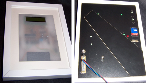
[Victor] may be onto something when it comes to project enclosures. He’s using a picture frame to house his electronics projects. This is made especially easy by the variety of sizes you can find at Ikea. Possibly the most important dimension is to have enough frame thickness to sandwich your components between the glass and the back plate of the frame.

The project seen here is a temperature data logger. The frosted diffuser covering everything but the LCD screen and gives you a glimpse of what’s mounted to the back panel. He connected the four different protoboard components, along with a battery pack, to each other use right angle pin headers. They were then strapped to the back plate of the frame by drilling some holes through which a bit of wire was threaded. He even cut a hole to get at the socket for the temperature sensor and to attach the power input. So that he doesn’t need to open the frame to get at the data, the SD card slot is also accessible. His depth adjustment was made by adding standoffs at each corner of the frame, and replacing the metal wedges that hold the back in place.

You don’t need to limit yourself with just one. This UV exposure rig uses three Ikea frames.

Script Lets You Import Eagle Boards For Use In FreeCAD

eagle-designs-imported-for-freecad

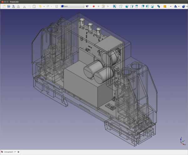
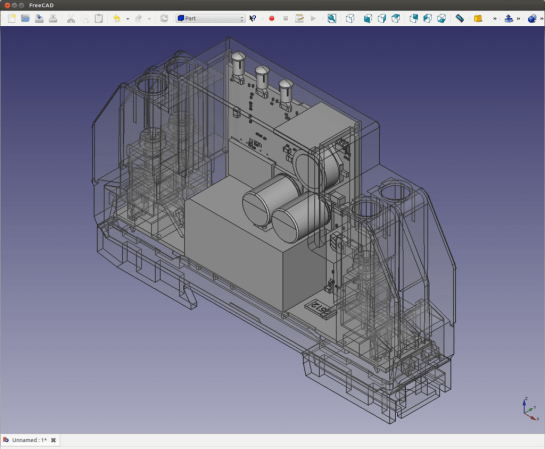
[Christian Aurich] wanted to use his Eagle CAD circuit board design in a proper CAD program in order to design enclosures. There are already a few options along these lines, but they didn’t quite fit his needs so he developed a script to import Eagle boards into FreeCAD. The script is packaged as a python macro for FreeCAD.

In describing the shortcomings of what’s already out there [Christian] does mention the use of EagleUp to model boards in Google SketchUp. But he feels the way the data is produced by SketchUp makes these models work well with 3D printing, but says they’re not easy to use with mechanical design CAD software. He also feels that the photo-realistic renderings are useless when developing enclosures.

It’s worth mentioning that this approach is only possible because CadSoft’s migration to XML makes it dead simple to get at the data.

Raspberry Pi Is Right At Home Inside Of A Game Boy

IMG_20130201_163325

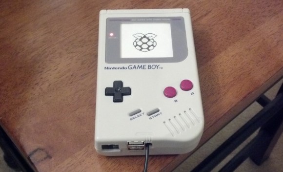
[Matt] still has his original Game Boy from when he was a kid. He wanted to pull it out and play some of the classics but alas, the screen was broken and he couldn’t find a source for a drop-in replacement. In the end he ordered a used unit and pulled the screen from that one. This left him with a pile of leftover Game Boy parts which turned into a Raspberry Pi case project.

Since the RPi doesn’t have a power switch he thought it would be pretty neat to incorporate the Game Boy power switch. He was able to cut out one section of the original PCB that included the switch and one mounting hole. This kept the switch aligned with the case and gave him some pads to solder the incoming USB cable and the jumper wires to the RPi board. In the image above the power LED is on. He mentions that there was an issue with that circuit; the voltage drop across the LED was messing up the feed to the Pi so it’s disabled for now.

We’ve embedded a couple of images of everything inside the case after the break. If you’re a fan of this hack you should also take a look at the Game Boy hard drive enclosure which uses the same pixel art printed on paper effect for the screen window.

Continue reading “Raspberry Pi Is Right At Home Inside Of A Game Boy”

Heating, Bending, And Gluing To Make Acrylic Enclosures

acrylic-enclosures-heating-bending-gluing

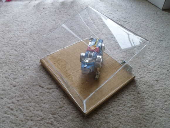
You can do a lot with acrylic and few tools. If you’re just starting out we’d suggest taking a look at [Michael Colombo’s] guide to heating, bending, and gluing to create custom acrylic enclosures. Chances are you already have most of what you need. The one tool you might be lacking is a heat gun.

The process starts with math. Before cutting the acrylic down to size you need to calculate how much you need. Next [Michael] demonstrates his cutting technique using a Dremel and a cut-off wheel. We prefer to clamp along the cut line, score many times with a razor knife, and snap the stuff. But you can also send it through a table saw if you have the right blade.

The bending technique he uses starts by clamping boards on either side of the bend. The acrylic left sticking out is pushed with a scrap board while the bend is heated with the heat gun. Once all of the corners were made in one piece the sides were glued in place. This last step can be tricky. The acrylic glue is made to work with perfect seams, so make sure your cuts are clean and the bent pieces line up.

The process was documented in the clip found after the jump. If you’re looking for a more targeted heat source check out this dedicated acrylic bender.

Continue reading “Heating, Bending, And Gluing To Make Acrylic Enclosures”

One Method Of Fabricating Translucent Faceplates

laser-cut-translucent-panel-covers

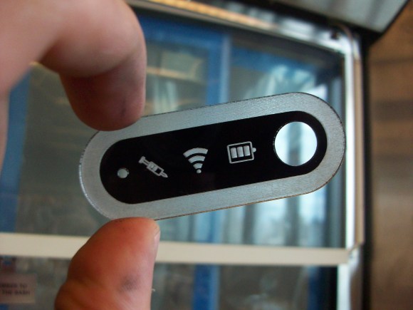
Enclosures are the bane of electronics engineers (or so says [Dave Jones] of the EEVblog and The Amp Hour). But fabricating a case that looks great has been getting easier lately. [Eric Forkosh] produced this professional-looking translucent face plate with a minimum of effort. He found a way to use a laser cutter to etch icons in acrylic.

Admittedly, this is not very involved. But just look at the quality he achieved. The secret to his success (aside from having a quality laser cutter on hand) is to use high-temperature spray paint. The acrylic is coated in paint and allowed to dry before heading to the laser cutter. By using the rasterize setting under low power he kills two birds with one stone; the paint is etched away while the acrylic is left a little bit rough to act as a diffuser for LEDs behind the panel. [Eric] cautions against using regular spray paint. In his write up he shows off the unsightly results of doing so.

This makes a great addition to some of the case options out there. One that we have been keeping our eye on is the Sick of Beige initiative being spearheaded by [Ian Lesnet].

Adventures In Mold Making And Making Your Own Enclosures

case

The folks at SC-3000 survivors have been working on a cartridge capable of storing dozens of games for the ancient Sega SC-3000 computer. The PCB works beautifully, but making a case for their cartridge left them with few options. They could use a 3D printer or simply collect a whole bunch of used cartridge cases, but making their own mold for a cartridge case was the best solution.

To create the mold for their multicart enclosure, the SC-3000 survivors first took an old, used case and made a silicone mold. While the first attempt at mold making was encouraging, several problems began to crop up due to the lack of vent holes and wiggling the mold before the resin had set. Before long, a proper technique to make resin casts was developed: use lots of resin, and don’t apply pressure or rubber bands to a curing mold.

We’re always impressed by what can be done with a few sheets of plastic, some Bondo, and the inordinate amounts of patience and sandpaper we see with other case mods and enclosure builds. the SC-3000 survivors put together an enclosure that rivals any Bondo build, and we’re happy they put out this tutorial.

Tutorial Designs 3D Printed Cases For Your Projects

[Landon Cox] recently finished up a 3-part tutorial on designing project enclosures for 3D printing. The series is great if you have not yet tried your hand at this realm of the 3D printing universe, but there’s a lot to take away about design and modeling even if you don’t plan to print your creations.

He starts off part one of the tutorial by explaining the need for 3D printed cases. He believes it’s the natural progression after you’ve made it far enough to have your own PCB manufactured. Why not add a well designed and fabricated case to compliment your meticulously laid out circuitry? In part two he gets the design ball rolling by modeling the top and bottom portions of the case seen above in blue. The final step is to design a face plate that matches the needs of your circuit; in this case it’s DB9 and RJ45 connectors.

It’s not all smooth sailing along the way. [Landon] does actually print the case and the faceplate is just a bit too big for the the rest of the enclosure. But better too big than too small as shaving away a bit of the edges fixes it right up.

[via Adafruit]