“Measure twice, cut once” is great advice in every aspect of fabrication, but perhaps nowhere is it more important than when building a CNC machine. When precision is the name of the game, you need measuring tools that will give you repeatable results and preferably won’t cost a fortune. That’s the idea behind this Arduino-based measuring jig for fabricating parts for a CNC build.
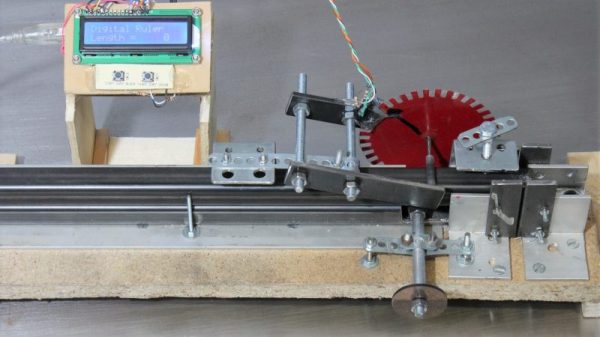
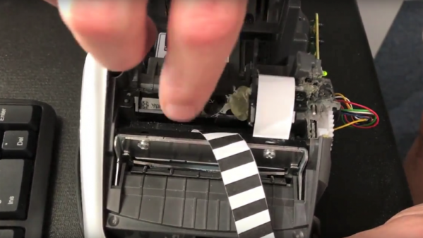
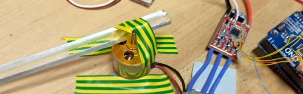
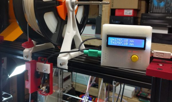
When it comes to building on the cheap, nobody holds a candle to [HomoFaciens]. We’ve seen his garbage can CNC build and encoders from e-waste and tin cans, all of which gave surprisingly good results despite incorporating such compliant materials as particle board and scraps of plumber’s strapping. Looking to build a more robust machine, he finds himself in need of parts of consistent and accurate lengths, so he built this jig. A sled of particle board and a fence of angle aluminum position the square tube stock, and a roller with a paper encoder wheel bears on the tube under spring pressure. By counting pulses from the optical sensors, he’s able to precisely position the tube in the jig for cutting and drilling operations. See it in action in the video after the break.
If you’ve been following [HomoFaciens], you’ll no doubt see where he’s been going — build a low-end tool, use that to build a better one, and so on. We’re excited to see him moving into more robust materials, but we’ll miss the cardboard and paperclip builds.
Continue reading “Arduino And Encoder Form Precision Jig For Cutting And Drilling”

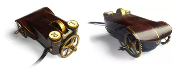
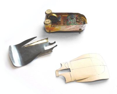 We were afraid the project would require advanced wood or metal working capability, but the bottom of the mouse is made from paper mache. The top and sides are cut from tinplate. Of course, the paint job is everything.


