When we first looked at [Anders Nielsen’s] EEPROM programmer project, it was nice but needed some software and manual intervention and had some limitations on the parts you could program. But through the magic of Open-Source collaboration, revision 2 of the project overcomes all of these limitations and—as you can see in the video below—looks very polished.
If you recall, the programmer is in a “shield” format that can plug into an Arduino or — if you prefer a retrocomputer — a 6502uno. Along with hardware improvements from the community, [Henrik Olsson] wrote Python software to handle the programming (see the second video below).
As we all know, when developing software for any platform or simply hacking a bit of code to probe how something works, the ability to deploy code rapidly is a huge help. [Martin Donlon], aka [wickerwaka], is well known in retro gaming and arcade hardware reverse engineering circles and had the usual issues figuring out how an arcade CPU board worked while developing a MiSTer core. Some interesting ASICs needed quite a bit of poking, and changing the contents of socketed ERPOMs is a labour-intensive process. The solution was PicoROM, a nicely designed ROM emulator in a handy DIP-32 form factor.
As the title suggests, PicoROM is based on the Raspberry Pi RP2040. It emulates an 8-bit ROM up to 2MBits in size with speeds up to 100ns. Since it uses the RP2040, USB connectivity is simple, enabling rapid uploading of new images to one (or more) PicoROMs in mere seconds. A vertically orientated USB-C connector allows multiple PicoROMs to be cabled to the host without interfering with neighbouring hardware. The firmware running on core 1 passes data from the internal 264K SRAM, using the PIO block as a bus interface to the target. A neat firmware feature is the addition of a mechanism to use a ROM region as a bidirectional control channel, which the software running on the target can use to communicate back to the host computer. This allows remote triggering of actions and the reporting of responses. Responses which may not be physically observable externally. [Martin] is using this feature extensively to help probe the functionality of some special function chips on the target boards, which is still a slow process but helped massively by reducing that critical software iteration time. The PCB was designed with KiCAD. The project files for which can be found here.
That EPROMs, EEPROMs and kin can be used as programmable logic should probably not come as a major surprise, but [Jimmy] has created a Lisp-based project that makes using these chips as a logic array very straightforward. All it takes is importing the package into one’s Lisp project and defining the logic, before the truth function generates the binary file that can be written to the target chip.
Suggested is the one-time-programmable AT27C512R EPROM (64k x8), but any 8-bit parallel interface (E)EPROM should work, with non-OTP chips being nice unless the chip has to go into a production device. A possible future improvement is the addition of 16-bit (E)EPROM support.
The use of EEPROMs is common with PLA-replacements, as with, for example, the Commodore 64, where the official PLA IC tends to go bad over time. Due to the complexity of the logic in these PLA ICs, here CPLDs are used, which internally are still EEPROM-based, but feature many more programmable elements to allow for more complex logic. If all you need is a bit of glue logic and you are looking for something in between a stack of 74-logic ICs and a CPLD, an EEPROM may be just be the solution, regardless of whether you prefer to create the binary image with Lisp or C.
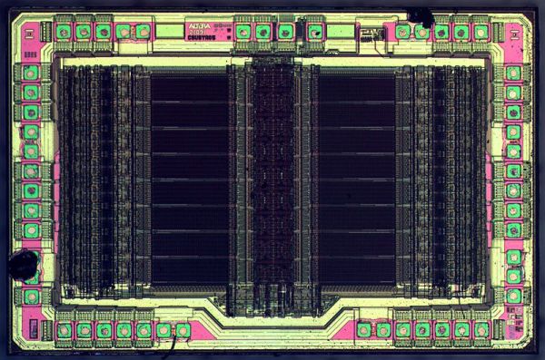
EPROMs, those UV-erasable memory chips of the 80s and 90s, once played a crucial role in countless electronic devices. They’ve become relics of a bygone era, but for enthusiasts of vintage electronics, the allure of these light-sensitive devices remains strong. Today, we’re diving into [Kevin Osborn]’s nostalgic journey as he uncovers the secrets of old EPROMs loaded with Atari 7800 code.
[Kevin] used to work at General Computer Company, which produced the Atari 7800 and several games for the system. Thus, he had a handful of old carts and development EPROMs sitting up in his attic along with an old console. Recently, he decided to try and uncover what was on the EPROMs and begun an investigation. They wouldn’t run in his Atari, and he quickly realized why: the EPROMs weren’t cryptographically signed, so the system wouldn’t load them. Continue reading “Working With Old High-Voltage EPROMs Is Fussy”→
Generating video signals is an exercise in periodicity. After all, an old-fashioned CRT just scans at a certain horizontal frequency and refreshes the entire screen each time it starts over. VGA is made to drive this technology. An EPROM chip can easily generate repeating patterns when driven by a counter at a known frequency.
As you might expect, there were a few software glitches to work out, but in the end, the circuit did its job, displaying a fixed image on a VGA monitor.
If you haven’t run into [Matt] before, he has a complete series on how he built a “wire-by-wire” Apple II clone. We will warn you, though. Don’t click on the link unless you have some spare time. The 18 videos take over two hours to work through, but there is some beautiful prototyping and a lot of good information in them.
An article on the history of EPROMs in the Soviet Union by [Vladimir Yakovlev] over at The CPU Shack Museum caught our attention. It is part one of a series on the topic, and walks you through the earliest Soviet EPROMs families.
The first of which, from the 1970s, is the K505RR1 developed and manufactured in Kyiv, equivalent to the first-generation Intel 1702A. It could hold 2048 bits, organized as 256×8, and offered a whopping 20 reprogramming cycles and data retention of 5000 hours.
The narrative proceeds to introduce several subsequent generations, design facilities, manufacturing techniques, and representative chip examples. A few tidbits — unlike Western EPROMs, the Soviets managed to put quartz windows in plastic packages (see the KP573 family).
In addition to the common gray or white, they also used different terracotta colored ceramic packages. An odd ceramic flat-pack EPROM is shown, and also some EPROMs whose dies have been painted over and re-badged as OTP chips.
Intel began producing EPROMs in 1971 as reported by the inventor, Intel’s Dov Frohman-Bentchkowsky, in Electronics Magazine’s 10 May edition (pg 91). We learned, amongst other things, that the 1701 did not have a quartz window, but could still be erased by exposure to X-rays. A friendly word of warning — browsing electronics advertisements from 50 years ago can easily consume your entire morning.
Once the package is sealed, information can still be erased by exposing it to X radiation in excess of 5×10⁴ rads, a dose which is easily attainable with commercial X-ray generators.
[Jason P], evidently an enjoyer of old reliable laser printing tech, spilled a drink (nitter) onto his Panasonic KX-P5400 SideWriter. After cleanup, everything worked fine — except that the PSU’s 5 V became 6.5 V during the accident, and the EPROM with LocalTalk interface firmware died, connection between VCC and GND seemingly interrupted inside the chip. Understandably, [Jason] went on Twitter, admitted the error of his ways, and sheepishly asked around for EPROM dumps.
Instead, [Manawyrm] wondered — would the chip have anti-ESD body diodes from GND to IO pins, by any chance? A diode mode multimeter check confirmed, yes! It was time for an outlandish attempt to recover the firmware. [Manawyrm] proposed that [Jason] connect all output pins but one to 5 V, powering the EPROM through the internal VCC-connected body diodes – reading the contents one bit at a time and then, combining eight dumps into a single image.
After preparing a TL866 setup, one hour of work and some PHP scripting later, the operation was a success. Apparently, in certain kinds of cases, dead ROM chips might still tell their tales! It’s not quite clear what happened here. The bond wires looked fine, so who knows where the connection got interrupted – but we can’t deny the success of the recovery operation! Need a primer on dumping EPROMs that are not dead? Here you go.