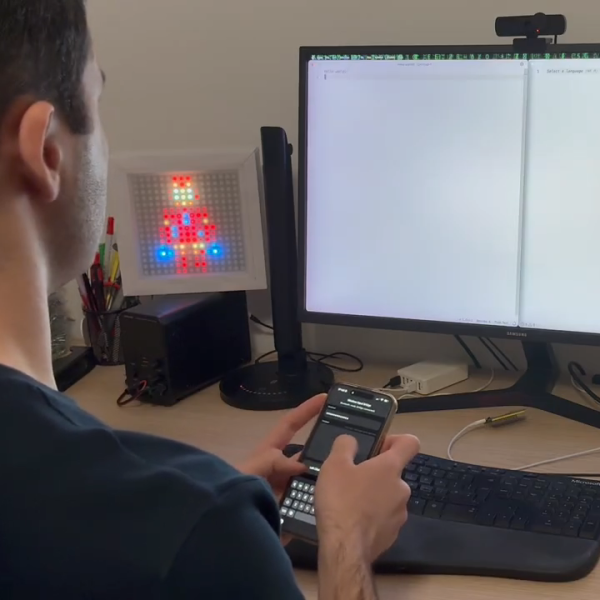
We don’t usually speculate on the true identity of the hackers behind these projects, but when [TN666]’s accoustic drone-detector crossed our desk with the name “Batear”, we couldn’t help but wonder– is that you, Bruce? On the other hand, with a BOM consisting entirely of one ESP32-S3 and an ICS-43434 I2S microphone, this isn’t exactly going to require the Wayne fortune to pull off. Indeed, [TN666] estimates a project cost of only 15 USD, which really democratizes drone detection.
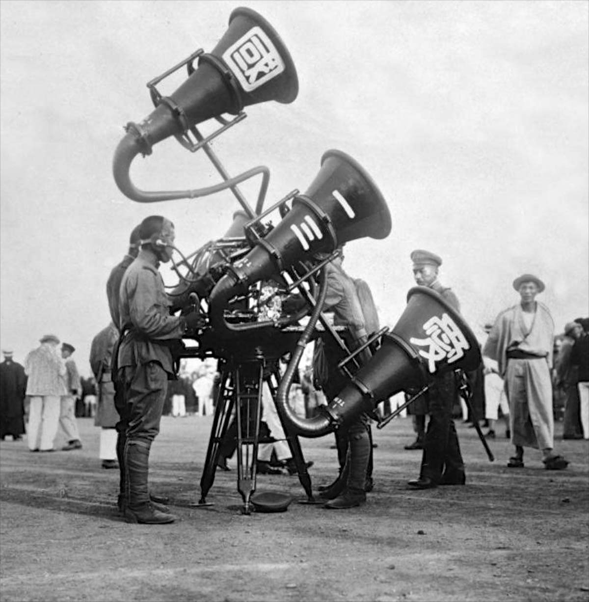
The key is what you might call ‘retrovation’– innovation by looking backwards. Most drone detection schema are looking to the ways we search for larger aircraft, and use RADAR. Before RADAR there were acoustic detectors, like the famous Japanese “war tubas” that went viral many years ago. RADAR modules aren’t cheap, but MEMS microphones are– and drones, especially quad-copters, aren’t exactly quiet. [TN666] thus made the choice to use acoustic detection in order to democratize drone detection.
Of course that’s not much good if the ESP32 is phoning home to some Azure or AWS server to get the acoustic data processed by some giant machine learning model. That would be the easy thing to do with an ESP32, but if you’re under drone attack or surveillance it’s not likely you want to rely on the cloud. There are always privacy concerns with using other people’s hardware, too. [TN666] again reached backwards to a more traditional algorithmic approach– specifically Goertzel filters to detect the acoustic frequencies used by drones. For analyzing specific frequency buckets, the Goertzel algorithm is as light as they come– which means everything can run local on the ESP32. They call that “edge computing” these days, but we just call it common sense.
The downside is that, since we’re just listening at specific frequencies, environmental noise can be an issue. Calibration for a given environment is suggested, as is a foam sock on the microphone to avoid false positives due to wind noise. It occurs to us the sort physical amplifier used in those ‘war tubas’ would both shelter the microphone from wind, as well as increase range and directionality.
[TN] does intend to explore machine learning models for this hardware as well; he seems to think that an ESP32-NN or small TensorFlow Lite model might outdo the Goertzel algorithm. He might be onto something, but we’re cheering for Goertzel on that one, simply on the basis that it’s a more elegant solution, one we’ve dived into before. It even works on the ATtiny85, which isn’t something you can say about even the lightest TensorFlow model.
Thanks to [TN] for the tip. Playboy billionaire or not, you can send your projects into the tips line to see them some bat-time on this bat-channel.