The retrocomputing crowd will go to great lengths to recreate the computers of yesteryear, and no matter which species of computer is being restored, getting it just right is a badge of honor in the community. The case and keyboard obviously playing a big part in that look, so when a crowdfunding campaign to create new keycaps for the C64 was announced, Commodore fans jumped to fund it. Sadly, more than four years later, the promised keycaps haven’t been delivered. One disappointed backer, Jim Drew, decided he was sick of waiting, so he delved into the world of keycaps injection molding and started his own competing campaign. Jim details his adventures in his Kickstarter Indiegogo campaign, which makes for good reading even if you’re not into Commodore refurbishment. Here’s hoping Jim has better luck than the competition did.
Looking for anonymity in our increasingly surveilled world? You’re not alone, and in fact, we predict facial recognition spoofing products and methods will be a growth industry in the new decade. Aside from the obvious – and often illegal – approach of wearing a mask that blocks most of the features machine learning algorithms use to quantify your face, one now has another option, in the form of a colorful pattern that makes you invisible to the YOLOv2 algorithm. The pattern, which looks like a soft-focus crowd scene rendered in Mardi Gras colors, won’t make the algorithm think you’re someone else, but it will prevent you from being classified as a person. It won’t work with any other AI algorithm, but it’s still an interesting phenomenon.
We saw a great hack come this week about using an RTL-SDR to track down a water leak. Clayton’s water bill suddenly skyrocketed, and he wanted to track down the source. Luckily, his water meter uses the encoder receive-transmit (ERT) protocol on the 900 MHz ISM band to report his usage, so he threw an SDR dongle and rtlamr at the problem. After logging his data, massaging it a bit with some Python code, and graphing water consumption over time, he found that water was being used even when nobody was home. That helped him find the culprit – leaky flap valves in the toilets resulting in a slow drip that ran up the bill. There were probably other ways to attack the problem, but we like this approach just fine.
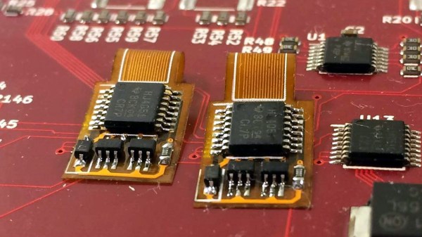
Are your flex PCBs making you cry? Friend of Hackaday Drew Fustini sent us a tip on teardrop pads to reduce the mechanical stress on traces when the board flexes. The trouble is that KiCad can’t natively create teardrop pads. Thankfully an action plugin makes teardrops a snap. Drew goes into a bit of detail on how the plugin works and shows the results of some test PCBs he made with them. It’s a nice trick to keep in mind for your flexible design work.
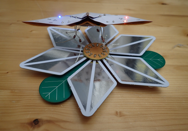
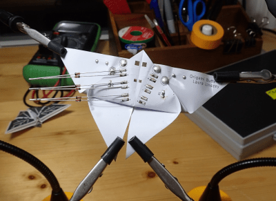 The idea she landed on is this: when the butterfly alights on a power-providing flower, it draws electrical nectar through its diode legs and lights up the LEDs on its wings. As long as one leg touches a ground petal and another touches a VIN petal, there will be light.
