There’s a piece of tech that many of us own, but very few of us have dissected. This is strange, given our community’s propensity for wielding the screwdriver, but how many of you have taken apart a camera lens. Even though many of us have a decent camera, almost none of us will have taken a lens to pieces because let’s face it, camera lenses are expensive!
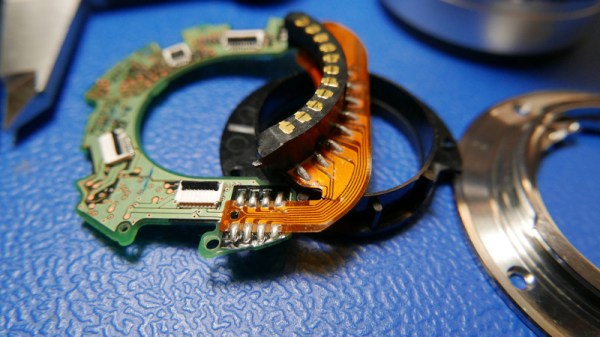
[Anthony Kouttron] has taken that particular plunge though, because in cleaning his Olympus lens he tore its internal ribbon cable from the camera connector to the PCB. Modern lenses are not merely optics in a metal tube, their autofocus systems are masterpieces of miniaturised electronics that penetrate the entire assembly.
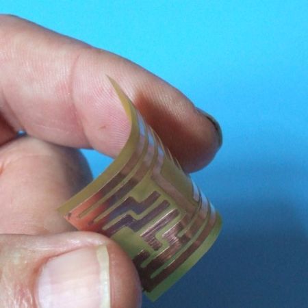
In normal circumstances this would turn the lens from a valued photographic accessory into so much junk, but his solution was to take the bold path of re-creating the torn cable in KiCad and have it made as a flexible PCB, and to carefully solder it back on to both connector and autofocus PCB. We applaud both the quality of his work, and thank him for the unusual glimpse into a modern lens system.
Lens repairs may be thin on the ground here, but we’ve had another in 2015 with this Nikon aperture fix.