An Open Source Modular Flexure Construction Set

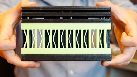
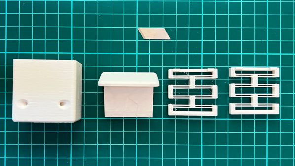
Flexures are one of those innocent-looking mechanisms that one finds inside practically any kind of consumer device. Providing constrained movements with small displacements, complete with controlled tension, they can be rather tricky to design. GrabCAD designer [Vyacheslav Popov] hails from Ukraine, and due to the current situation there, plans to sell a collection of flexure building blocks became difficult. In the end, [Vyacheslav] decided to generously release his work open source, for all to enjoy. This collection is quite extensive, looking like it could solve a huge variety of flexure design problems. (Links to the first three sets: Set00Set01Set02 but check the author’s collection page for many others)

It’s not just those super-cheap mechanisms in throw-away gadgets that leverage flexures, it’s much more. The Mars rovers use flexure-based suspension, scientific instruments (interferometers and the like) make use of them for small motions where specific axis constraints are needed, and finally, MEMS accelerometers and gyroscopes are based entirely upon them. We’re not even going to try to name examples of flexures in the natural world. They’re everywhere. And, now we’ve got some more design examples to use, so why not flex your flexure muscles and send one to the 3D printer and have a play?

We see flexures here quite a bit, like this nice demonstration of achievable accuracy. Flexures can make some delicious mechanisms, and neat 3D printable input devices.

Thanks to [Addison] for the tip!

Filament Cutter Uses Unusual (But Effective) 3D-Printed Spring Design

When one needs a spring, a 3D-printed version is maybe not one’s first choice. It might even be fair to say that printed springs are something one ends up making, rather than something one sets out to use. That might change once you try the spring design in [the_ress]’s 3D-printed filament cutter with printed springs.

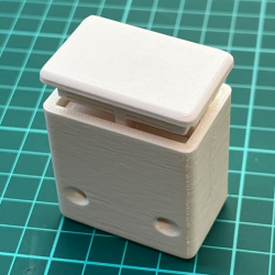
The filament cutter works like this: filament is inserted into the device through one of the pairs of holes at the bottom. To cut the filment, one presses down on the plunger. This pushes a blade down to neatly cut the filament at an angle. The cutter is the device’s only non-printed part; a single segment from an 18 mm utility knife blade.

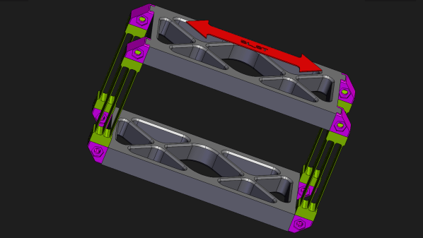
The springs are of particular interest, and don’t look quite like a typical spring. They take their design from this compliant linear motion mechanism documented on reprap.org, and resemble little parallel 4-bar linkages. These springs have limited travel, but are definitely springy enough for the job they need to do, and that’s the important part.

Want a more traditional coiled spring? Annealing filament wound around a mandrel can yield useful results, and don’t forget the fantastic mechanisms known as flexures; they have clear similarities to the springs [the_ress] used. You can see her design in action in the short video, embedded below.

Continue reading “Filament Cutter Uses Unusual (But Effective) 3D-Printed Spring Design”

3D Printed Flexure Shows Precision In Action

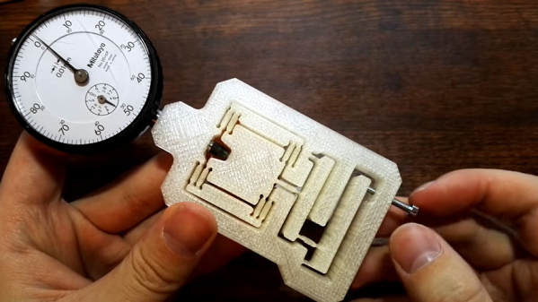
Here’s an older but fantastic video that is as edifying as it is short. [Topias Korpi] demonstrates a 3D printed flexure with a dial indicator on one end, and an M3 screw on the other. As the screw is turned, the dial indicator moves steadily with roughly a 15:1 reduction between the movement of the screw and the indicator. Stable deflections of 0.01 mm are easily dialed in, and it’s neat seeing it work while the flexure itself shows no perceptible movement. A demonstration is embedded below the page break and is less than a minute long, so give it a watch and maybe get some ideas.

Flexures are fantastic designs capable of a wide variety of physical functions, and just as [Topias]’s demonstration shows, they can be a natural complement to 3D printing. In fact, flexures are an important part of the design and function of JWST’s mirror actuators, which are responsible for making astonishingly small adjustments to each of the space telescope’s 18 mirror sections.

Continue reading “3D Printed Flexure Shows Precision In Action”

Flexures Make This Six-DOF Positioner Accurate To The Micron Level

It’s no secret that we think flexures are pretty cool, and we’ve featured a number of projects that leverage these compliant mechanisms to great effect. But when we saw flexures used in a six-DOF positioner with micron accuracy, we just had to dig a little deeper.

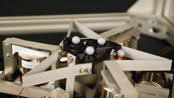
The device is known as the Hexblade, and it comes to us from the lab of [Jonathan Hopkins] at UCLA. We have to admit that at times, the video below feels a little like the “Turbo Encabulator” schtick — “three identical decoupled actuation limbs arranged in an axisymmetric configuration” may be perfectly descriptive, but it does not flow trippingly from the tongue. Hats off to [Professor Hopkins] for nailing the narration, though, and really, once you get a handle on the jargon, it all makes perfect sense. The platform is supported by a total of six flexures, which look like bent pieces of sheet metal but are actually cut from a solid block of material using wire EDM. Three of the flexures are oriented in the plane of the platform, while the other three are perpendicular to it. The far end of each flexure is connected to a voice-coil actuator that is surrounded by another flexure, this one in a parallelogram arrangement. The six actuators can move the platform smoothly through three linear translations (X, Y, and Z) and three rotations (roll, pitch, and yaw).
The platform’s range of motion is limited, but the advantages of using flexures as bearings are clear — there’s no backlash or hysteresis, and the voice coils can control the position of the stage to micron accuracy. Something like the Hexblade would be an ideal positioner for microscopy, and we can imagine an even smaller version, perhaps even a MEMS-fabricated one for nanomanufacturing applications. The original concept of the Hexblade serving as the print head for a fabrication robot for space applications is pretty cool, too, and we’d venture to say that a homebrew version of this probably isn’t out of reach either.

Continue reading “Flexures Make This Six-DOF Positioner Accurate To The Micron Level”

JWST mirror actuator model

Working Model Reveals Amazing Engineering Of Webb’s Mirror Actuators

We end up covering a lot of space topics here on Hackaday, not because we’re huge space nerds — spoiler alert: we are — but because when you’ve got an effectively unlimited budget and a remit to make something that cannot fail, awe-inspiring engineering is often the result. The mirror actuators on the James Webb Space Telescope are a perfect example of this extreme engineering, and to understand how they work a little better, [Zachary Tong] built a working model of these amazing machines.

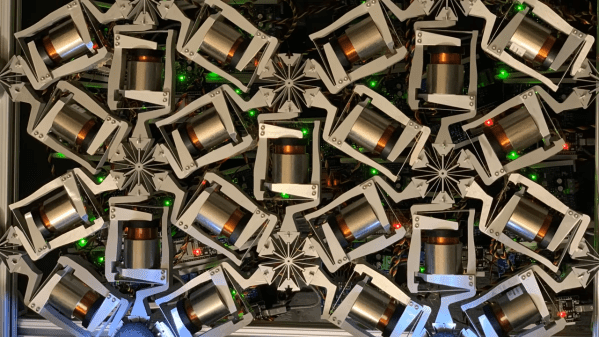
The main mirror of the JWST is made of 18 separate hexagonal sections, the position of each which must be finely tuned to make a perfect reflector. Each mirror has seven actuators that move it through seven degrees of freedom — the usual six that a Stewart platform mechanism provides, plus the ability to deform the mirror’s curvature slightly. [Zach]’s model actuator is reverse-engineered from public information (PDF) made available by the mirror contractor, Ball Aerospace. While the OEM part is made from the usual space-rated alloys and materials, the model is 3D printed and powered by a cheap stepper motor.

That simplicity belies the ingenious mechanism revealed by the model. The actuators allow for both coarse and fine adjustments over a wide range of travel. A clever tumbler mechanism means that only one motor is needed for both fine and coarse adjustments, and a flexure mechanism is used to make the fine adjustments even finer — a step size of only 8 nanometers!

Hats off to [Zach] for digging into this for us, and for making all his files available in case you want to print your own. You may not be building a space observatory anytime soon, but there’s plenty about these mechanisms that can inform your designs.

Continue reading “Working Model Reveals Amazing Engineering Of Webb’s Mirror Actuators”

Bendy Straws

Compliant Mechanisms Hack Chat

Join us on Wednesday, January 26 at noon Pacific for the Compliant Mechanisms Hack Chat with Amy Qian!

When it comes to putting together complex mechanisms, we tend to think in a traditional design language that includes elements like bearings, bushings, axles, pulleys — anything that makes it possible for separate rigid bodies to move against each other. That works fine in a lot of cases — our cars wouldn’t get very far without such elements — but there are simpler ways to transmit force and motion, like compliant mechanisms.

Compliant mechanisms show up in countless products, from the living hinge on a cheap plastic box to the nanoscale linkages etched into silicon inside a MEMS accelerometer. They reduce complexity by putting the elasticity of materials to work and by reducing the number of parts it takes to create an assembly. And they can help make your projects easier and cheaper to build — if you know the secrets of their design.

join-hack-chatAmy Qian, from the Amy Makes Stuff channel on YouTube,  is a mechanical engineer with an interest in compliant mechanisms, so much so that she ran a workshop about them at the 2019 Superconference. She’ll stop by the Hack Chat to share some of what she’s learned about compliant mechanisms, and to help us all build a little flexibility into our designs.

Our Hack Chats are live community events in the Hackaday.io Hack Chat group messaging. This week we’ll be sitting down on Wednesday, January 26 at 12:00 PM Pacific time. If time zones have you tied up, we have a handy time zone converter.


Continue reading “Compliant Mechanisms Hack Chat”