Reverse Engineering The Nintendo Wavebird

Readers who were firmly on Team Nintendo in the early 2000’s or so can tell you that there was no accessory cooler for the Nintendo GameCube than the WaveBird. Previous attempts at wireless game controllers had generally either been sketchy third-party accessories or based around IR, and in both cases the end result was that the thing barely worked. The WaveBird on the other hand was not only an official product by Nintendo, but used 2.4 GHz to communicate with the system. Some concessions had to be made with the WaveBird; it lacked rumble, was a bit heavier than the stock controllers, and required a receiver “dongle”, but on the whole the WaveBird represented the shape of things to come for game controllers.

Finding the center frequency for the WaveBird

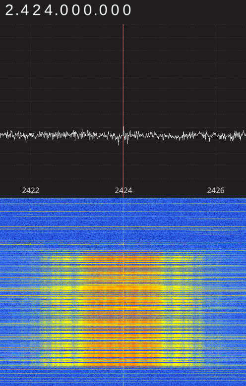
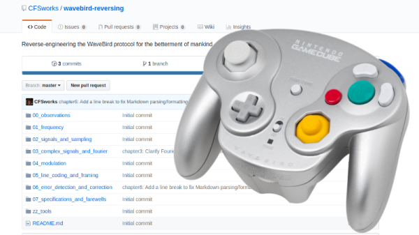
Given the immense popularity of the WaveBird, [Sam Edwards] was somewhat surprised to find very little information on how the controller actually worked. Looking for a project he could use his HackRF on, [Sam] decided to see if he could figure out how his beloved WaveBird communicated with the GameCube. This moment of curiosity on his part spawned an awesome 8 part series of guides that show the step by step process he used to unlock the wireless protocol of this venerable controller.

Even if you’ve never seen a GameCube or its somewhat pudgy wireless controller, you’re going to want to read though the incredible amount of information [Sam] has compiled in his GitHub repository for this project.

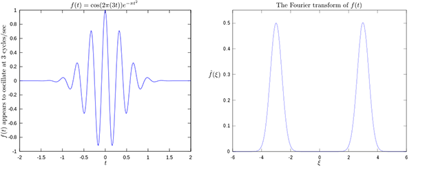
Starting with defining what a signal is to begin with, [Sam] walks the reader though Fourier transforms, the different types of modulations, decoding packets, and making sense of error correction. In the end, [Sam] presents a final summation of the wireless protocol, as well as a simple Python tool that let’s the HackRF impersonate a WaveBird and send button presses and stick inputs to an unmodified GameCube.

This amount of work is usually reserved for those looking to create their own controllers from the ground up, so we appreciate the effort [Sam] has gone through to come up with something that can be used on stock hardware. His research could have very interesting applications in the world of “tool-assisted speedruns” or even automating mindless stat-grinding.

Control System Fundamentals By Video

If you’ve had the classic engineering education, you probably have a hazy recollection of someone talking about control theory. If you haven’t, you’ve probably at least heard of PID controllers and open loop vs closed loop control. If you don’t know about control theory or even if you just want a refresher, [Brian Douglas] has an excellent set of nearly 50 video lectures that will give you a great introduction to the topic. You can watch the first lecture, below.

You might think that control systems are only useful in electronics when you are trying to control a process like a chemical plant or a temperature. However, control theory shows up in a surprising number of places from filters to oscillators, to the automatic gain control in a receiver. You’ll find the background behind many familiar results inside control theory. Sort of like when you take calculus and you discover how they came up with all the formulas you memorized in geometry.

Continue reading “Control System Fundamentals By Video”

Lock In Amplifiers

If you have about an hour to kill, you might want to check out [Shahriar’s] video about the Stanford Research SR530 lock in amplifier (see below). If you know what a lock in amplifier is, it is still a pretty interesting video and if you don’t know, then it really is a must see.

Most of the time, you think of an amplifier as just a circuit that makes a small signal bigger in some way — that is, increase the voltage or increase the current. But there are whole classes of amplifiers designed to reject noise and the lock in amplifier is one of them. [Shahriar’s] video discusses the math theory behind the amplifier, shows the guts, and demonstrates a few experiments (including measuring the speed of sound), as well.

Continue reading “Lock In Amplifiers”

Fourier Machine Mimics Michelson Original In Plywood

It’s funny how creation and understanding interact. Sometimes the urge to create something comes from a new-found deep understanding of a concept, and sometimes the act of creation leads to that understanding. And sometimes creation and understanding are linked together in such a way as to lead in an entirely new direction, which is the story behind this plywood recreation of the Michelson Fourier analysis machine.

For those not familiar with this piece of computing history, it’s worth watching the videos in our article covering [Bill “The Engineer Guy” Hammack]’s discussion of this amazing early 20th-century analog computer. Those videos were shown to [nopvelthuizen] in a math class he took at the outset of degree work in physics education. The beauty of the sinusoids being created by the cam-operated rocker arms and summed to display the output waveforms captured his imagination and lead to an eight-channel copy of the 20-channel original.

Working with plywood and a CNC router, [nopvelthuizen]’s creation is faithful to the original if a bit limited by the smaller number of sinusoids that can be summed. A laser cutter or 3D printer would have allowed for a longer gear train, but we think the replica is great the way it is. What’s more, the real winners are [nopvelthuizen]’s eventual physics students, who will probably look with some awe at their teacher’s skills and enthusiasm.

Continue reading “Fourier Machine Mimics Michelson Original In Plywood”

A DIY Fourier Transform Spectrometer

Typical spectrometers use prisms or diffraction gratings to spread light over a viewing window or digital sensor as a function of frequency. While both prisms and gratings work very well, there are a couple of downsides to each. Diffraction gratings produce good results for a wide range of wavelengths, but a very small diffraction grating is needed to get high-resolution data. Smaller gratings let much less light through, which limits the size of the grating. Prisms have their own set of issues, such as a limited wavelength range. To get around these issues, [iliasam] built a Fourier transform spectrometer (translated), which operates on the principle of interference to capture high-resolution spectral data.

[iliasam]’s design is built with an assortment of parts including a camera lens, several mirrors, a micrometer, laser diode, and a bunch of mechanical odds and ends. The core of the design is a Michelson interferometer which splits and recombines the beam, forming an interference pattern. One mirror of the interferometer is movable, while the other is fixed. [iliasam]’s design uses a reference laser and photodiode as a baseline for his measurement, which also allows him to measure the position of the moving mirror. He has a second photodiode which measures the interference pattern of the actual sample that’s being tested.

Despite its name, the Fourier transform spectrometer doesn’t directly put out a FFT. Instead, the signal from both the reference and measurement photodiodes is passed into the sound card of a computer. [iliasam] wrote some software that processes the sampled data and, after quite a bit of math, spits out the spectrum. The software isn’t as simple as you might think – it has to measure the reference signal and calculate the velocity of the mirror’s oscillations, count the number of oscillations, frequency-correct the signal, and much more. After doing all this, his software calculates an interferogram, performs an inverse Fourier transform, and the spectrum is finally revealed. Check out [iliasam]’s writeup for all the theory and details behind his design.

Harmonic Analyzer Mechanical Fourier Computer

If you’re into mechanical devices or Fourier series (or both!), you’ve got some serious YouTubing to do.

[The Engineer Guy] has posted up a series of four videos (Introduction, Synthesis, Analysis, and Operation) that demonstrate the operation and theory behind a 100-year-old machine that does Fourier analysis and synthesis with gears, cams, rocker-arms, and springs.

In Synthesis, [The Engineer Guy] explains how the machine creates an arbitrary waveform from its twenty Fourier components. In retrospect, if you’re up on your Fourier synthesis, it’s pretty obvious. Gears turn at precise ratios to each other to create the relative frequencies, and circles turning trace out sine or cosine waves easily enough. But the mechanical spring-weighted summation mechanism blew our mind, and watching the machine do its thing is mesmerizing.

In Analysis everything runs in reverse. [The Engineer Guy] sets some sample points — a square wave — into the machine and it spits out the Fourier coefficients. If you don’t have a good intuitive feel for the duality implied by Fourier analysis and synthesis, go through the video from 1:50 to 2:20 again. For good measure, [The Engineer Guy] then puts the resulting coefficient estimates back into the machine, and you get to watch a bunch of gears and springs churn out a pretty good square wave. Truly amazing.

The fact that the machine was designed by [Albert Michelson], of Michelson-Morley experiment fame, adds some star power. [The Engineer Guy] is selling a book documenting the machine, and his video about the book is probably worth your time as well. And if you still haven’t gotten enough sine-wavey goodness, watch the bonus track where he runs the machine in slow-mo: pure mechano-mathematical hotness!

Continue reading “Harmonic Analyzer Mechanical Fourier Computer”

FFT On The Raspi’s GPU

fft

The Raspberry Pi has been around for two years now, and still there’s little the hardware hacker can actually do with the integrated GPU. That just changed, as the Raspberry Pi foundation just announced a library for Fourier transforms using the GPU.

For those of you who haven’t yet taken your DSP course, fourier transforms take a function (or audio signal, radio signal, or what have you) and output the fundamental frequency. It’s damn useful for everything from software defined radios to guitar pedals, and the new GPU_FFT library is about ten times faster at this task than the Raspi’s CPU.

You can get a copy of  the GPU_FFT library by running rpi-update on your pi. If you happen to build anything interesting – something with a software defined radio or even a guitar pedal – you’re more than welcome to send it in to the Hackaday tips line. We’d love to see what you’re up to.