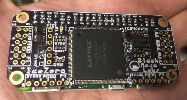
[Kevinhub] noticed there were quite a few FPGA hats for the Raspberry Pi. Instead going out and buying one of these boards like a filthy commoner, he decided to spin up his own FPGA Pi accessory. This IceZero FPGA board combines the best features from other FPiGA boards, and does it in a form factor that fits right on top of the minuscule Pi Zero.
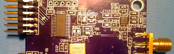
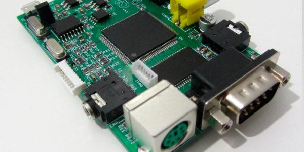
If you think slapping a Lattice FPGA onto a Pi has been done before, you’re right. Here’s a hat for the Pi using an iCE5LP4K-SG48, an FPGA with 3520 LUTs. The CAT Board from Xess has a slightly bigger FPGA with 7680 logic cells, and the FleaOhm has a monster FPGA on board that costs about $70 USD.
[Kevin]’s IceZero is at the lower end of these Raspberry Pi FPGA hats, using a Lattice ICE40HX4K. That’s only 3520 logic cells, but it only costs about $7 USD in quantity one. The board design is a standard two layer board that shouldn’t be too terrible for hand soldering. The boards are shared on OSH Park, should you want to test this little guy out.
This Pi Hat is specifically designed to be used with Project IceStorm, the Open toolchain for Lattice’s iCE40 FPGAs. That means there’s already a few projects out in the wild that can be easily ported to this platform, and already [Kevin] has a logic SUMP example going on his board.