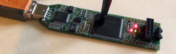
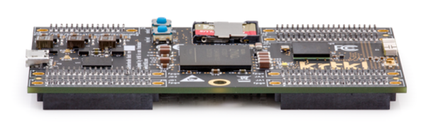
Mystery FPGA Circuit Feels The Pressure

You have an FPGA circuit and you want the user to interact with your circuit by pushing a button. Clearly, you need a button, right? Not so fast! [Clifford Wolf] recently found a mysterious effect that lets him detect when someone pushes on his iCEstick board.

The video below shows the mystery circuit (which is just the stock iCEstick board), which appears to react any time you flex the PC board. The Verilog implements a simple ring oscillator (basically an inverter with its output tied to its input).

Continue reading “Mystery FPGA Circuit Feels The Pressure”

Learn Flip Flops With (More) Simulation

In the previous installment, we talked about why flip flops are such an important part of digital design. We also looked at some latch circuits. This time, I want to look at some actual flip flops–that is circuit elements that hold their state based on some clock signal.

Just like last time, I want to look at sequential building blocks in three different ways: at the abstraction level, at the gate level, and then using Verilog and two online tools that you can also use to simulate the circuits. Remember the SR latch? It takes two inputs, one to set the Q output and the other to reset it. This unassuming building block is at the heart of many other logic circuits.

circ5A common enhancement to the SR latch is to include an enable signal. This precludes the output from changing when the enable signal is not asserted. The implementation is simple. You only need to put an additional gate on each input so that the output of the gate can’t assert unless the other input (the enable) is asserted. The schematic appears on the right.

In the case of this simulation (or the Verilog equivalent), the SR inputs become active high because of the inversion in the input NAND gates. If the enable input is low, nothing will change. If it is high, then asserted inputs on the S or R inputs will cause the latch to set or reset. Don’t set both high at the same time when the enable is high (or, go ahead–it is a simulation, so you can’t burn anything up).(Note: If you can’t see the entire circuit or you see nothing in the circuit simulator, try selecting Edit | Centre Circuit from the main menu.)

Continue reading “Learn Flip Flops With (More) Simulation”

DisplayPort With An FPGA

One of the challenges with display technology is the huge increase in bandwidth that has occurred since LCD panels took over from Cathode Ray Tubes. Low end laptops have a million pixels, UHD (“4K”) displays
have 8 million and the latest Full Ultra HD (“8k”) displays have over 33 million pixels. Updating all those pixels takes a lot of bandwidth – to update a 4k display at 60 Hz refresh rates takes close to a gigabyte per second. 8 billion bits – that is a lot of bits! That’s why VGA ports and even DVI ports are starting to vanish in favor of standards like HDMI and DisplayPort.

The current release of HDMI is 2.0, and is tightly licensed with NDAs and licensing fees. VESA, who created the DisplayPort standard, states the standard is royalty-free to implement, but since January 2010, all new DisplayPort related standards issued by VESA are no longer available to non-members.

So after receiving a new Digilent Nexys Video FPGA development board, Hackaday regular [Hamster] purchased a UHD monitor, scoured the internet for an old DisplayPort 1.1 standard, and started hacking.

A couple of months and 10,000 lines of VHDL code later what may be the first working Open Source DisplayPort
implementation is available. The design includes a 16-bit scrambler, an 8b/10b encoder, and multichannel support.

Continue reading “DisplayPort With An FPGA”

Learn Flip Flops With Simulation

Digital design with combinatorial gates like AND, OR, and NOT gates is relatively straightforward. In particular, when you use these gates to form combinatorial logic, the outputs only depend on the inputs. The previous state of the outputs isn’t important in combinatorial logic. While this is simple, it also prevents you from building things like state machines, counters, and even CPUs.

Circuits that use their own outputs as inputs are known as sequential circuits. It is true that at the fundamental level, sequential circuits use conventional logic gates. However, you usually won’t deal with them as gates, but will deal with abstractions like latches, flip flops, and even higher level constructs. Learning about these higher level constructs will allow you to make more advanced digital designs that are robust. In fact, if you are using an FPGA, building blocks like flip flops are essential since a large portion of the chip will be made up of some kind of flip flop.

Continue reading “Learn Flip Flops With Simulation”

FPGA CNC

When you think of a CNC controller you probably think of a PC with a parallel port or some microcontroller-based solution like a Smoothie Board. [Mhouse1] has a different idea: use FPGAs as CNC controllers.

FPGAs inherently handle things in parallel, so processing G code, computing curves and accelerations, and driving multiple stepper motors at one time would not be an issue at all for an FPGA. Most computer-based designs will have slight delays when trying to drive everything at once and this introduces some mechanical jitter. Even worse jitter occurs when you have an old PC trying to run everything when some other task takes over the CPU.

Continue reading “FPGA CNC”

Video FPGA With No External A/D

You have an old PC with a nonstandard RGB video out and you need to bring it to a modern PAL TV set. That’s the problem [svofski] had, so he decided to use an Altera-based DE1 board to do the conversion. Normally, you’d expect reading an RGB video signal would take an analog to digital converter, which is not typically present on an FPGA. Instead of adding an external device, [svofski] used a trick to hijack the FPGA’s LVDS receivers and use them as comparators.

Continue reading “Video FPGA With No External A/D”

Learning Verilog For FPGAs: Hardware At Last!

Getting into FPGA design isn’t a monolithic experience. You have to figure out a toolchain, learn how to think in hardware during the design, and translate that into working Verliog. The end goal is getting your work onto an actual piece of hardware, and that’s what this post is all about.

In the previous pair of installments in this series, you built a simple Verilog demonstration consisting of an adder and a few flip flop-based circuits. The simulations work, so now it is time to put the design into a real FPGA and see if it works in the real world. The FPGA board we’ll use is the Lattice iCEstick, an inexpensive ($22) board that fits into a USB socket.

Like most vendors, Lattice lets you download free tools that will work with the iCEstick. I had planned to use them. I didn’t. If you don’t want to hear me rant about the tools, feel free to skip down to the next heading.

Continue reading “Learning Verilog For FPGAs: Hardware At Last!”