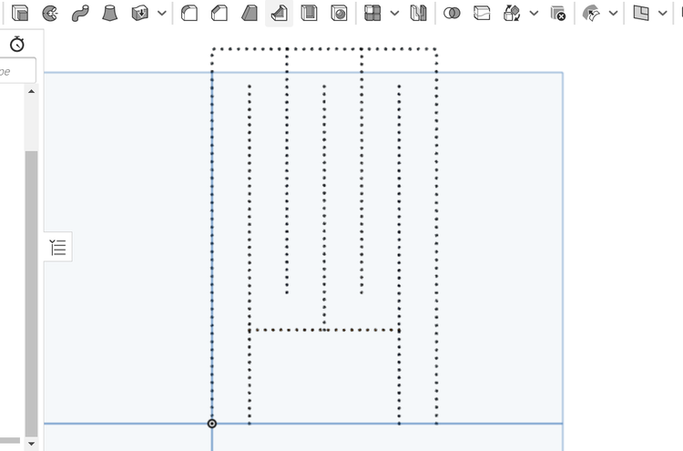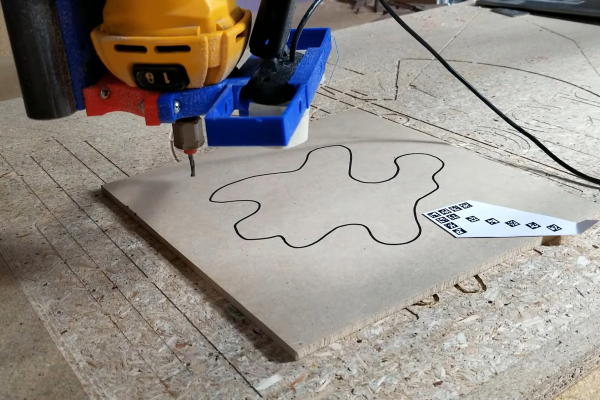
[Jamie] aka [vector76] hit us with a line-tracing plugin for OctoPrint that cuts out whatever 2D shape you draw on a piece of wood. The plugin lets you skip the modeling step entirely, going straight from a CNC-mounted webcam that reads your scribbles and gives you a Gcode toolpath in return. The code is on GitHub and there’s a demo video embedded below.
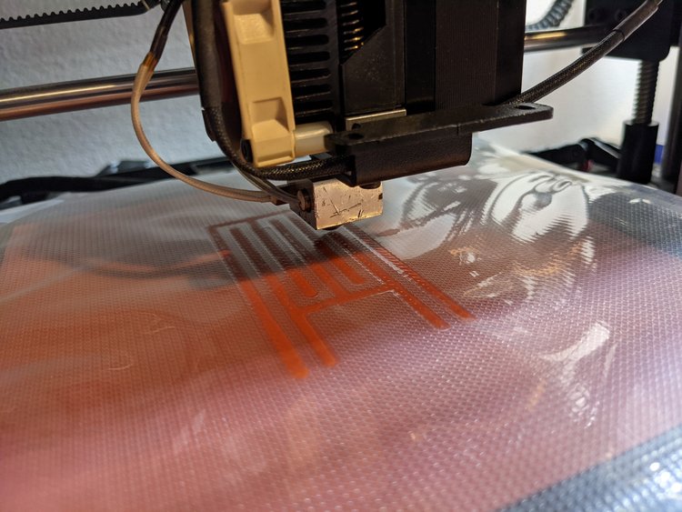
 Under the hood, OpenCV is doing a lot of the image processing, including line detection, and the iterative “find the line” and “move the toolhead” steps really show off what computer vision can do. It starts off with a fiducial arrow for scale and orientation, then it mores the webcam around the scene. The user can enter the usual milling parameters: speeds, feeds, depth of cut, tool offset, milling direction, etc. And then it gets to work.
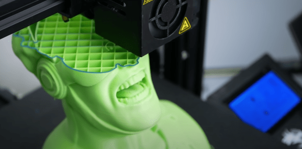
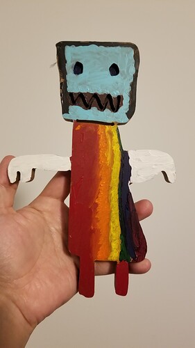
Right now, it’s limited to paths with non-crossing lines, and probably with good contrast and a nice dark line — all the usual CV restrictions. But mounting a webcam to a CNC toolhead and using it for various pathing problems really opens up tons of possibilities: visual homing, workpiece edge finding, copying parts, custom fitting odd shapes, and more. This project is clearly an invitation to keep on hacking, an appetizer. Once you see the girl pirate robot that [Jamie]’s daughter made, you’ll get the idea.
We’ve seen a similar OpenCV approach used for center-finding bore holes, but while we’ve seen a few webcams used with laser cutters, the CNC mill applications seem largely untapped. Let us know in the comments if you’ve got some other good examples.