While computers have become ever faster and more capable over the years, it’s hard to say they’ve become any more exciting. In fact, they’ve become downright boring. Desktop, laptop, or mobile, they’re all more or less featureless slabs of various dimensions. There’s not even much in the way of color variation — the classic beige box is now available with white, black, or metallic finishes.
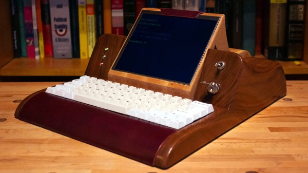
Believing that such a pedestrian appearance isn’t befitting a device that puts the world’s collected knowledge at our fingertips, [Keegan McNamara] started exploring a more luxurious approach to computing. Gone is the mass produced injection molded plastic, in its place is hand-carved maple and Tuscan leather. Common computing form factors are eschewed entirely for a swooping console inspired by fine furniture and classic sports cars. The final result, called the Mythic I, is equal parts art and science. Not just a bold reimaging of what a computer can be, but an object to be displayed and discussed. Continue reading “Mythic I: An Exploration Of Artisanal Computing”→
What’s the most important part of the keycap? The average user-who-cares might tell you it’s the look and feel, but a keyboard builder would probably say the mounting style. That’s where the rubber meets the road, after all. For anyone trying to make their own keycaps, ‘the mount itself’ is definitely the correct answer. Try printing your own keycaps, and you’ll learn a lot about tolerances when it comes to getting the mount right.
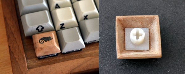
Conversely, you could use a subtractive process like a wood mill to make keycaps. Sounds easy enough, right? But what about all of us who don’t have access to one? [cbosdonnat], who has no CNC, has blazed a cellulose trail, combining hand-tooled wooden keycaps with 3D-printed mounts to create fully-customized keycaps. It’s a great project with concise how-to, especially when it comes to building the jigs needed to keep the keycaps consistently sized and shaped.
It makes a whole lot of sense to start by hollowing out the bottom instead of shaping the business side first or even cutting out the key shape, since the mount is mechanically vital. Why waste time on the look and feel if the foundation isn’t there yet?
Hardwood is a must for DIY keycaps, because the walls need to be thin enough to both fit over the switch and within the matrix, and be sturdy enough not to break with use. We love the look of the varnish-transferred laser-printed logo, and only wish there was a video so we could hear the clacking.
There are all kinds of ways to put legends on DIY keycaps, like waterslide decals for instance.
We’ve often heard it said that springs come in in all shapes and sizes…except for the one you need. In light of this, the hardware hacker would do well to keep the tools and knowledge required to make a custom spring close at hand when building something that moves. Luckily, all it really take is some stiff metal wire, a rod, and patience.
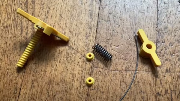
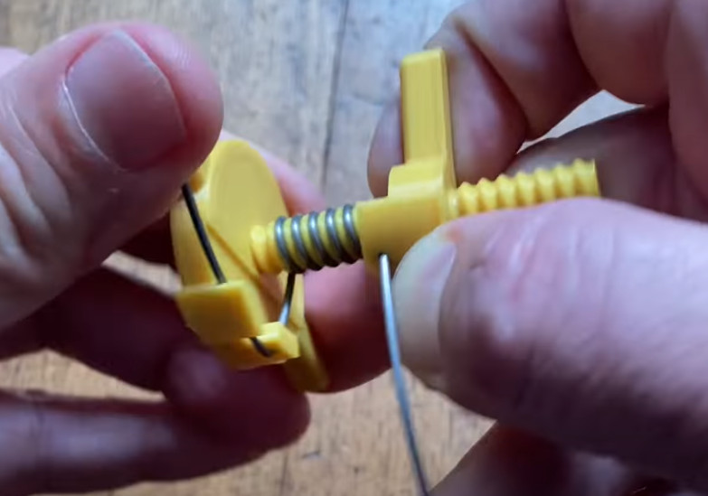
Unless you’ve got a 3D printer, that is. In which case, we’d suggest you print out this very clever “Spring Factory” designed by [Vincent Baillet]. The simple tool, consisting of just two parts, makes it easier and faster to make consistent DIY springs when compared to traditional methods. Rather than trying to eyeball the spacing of the coil as you wind the wire around the mandrel, this design does it for you.
As seen in the video, springs made with this tool look very professional. Not only does the threaded mandrel keep the spacing between coils even, it also makes sure all the springs you produce are identical. This can be especially important with projects that need to use multiple matching springs. [Vincent] says his handy tool works with piano wire from 0.8 to 1.2 mm, and slightly thicker if plain steel.
Of course, the obvious flaw in a tool like this is that it can only be used to make springs of a specific diameter. Changing the length is easy enough, just use more or less wire. But to make a thinner or thicker spring, you’d need a different size of mandrel. It seems that [Vincent] has only released the gadget in this approximately 9 mm diameter so far, but here’s hoping a few more sizes get added to the mix before too long.
Looking for something a bit more advanced? This Arduino-powered wire bender is capable of making some very impressive custom springs, among other things.
LinuxCNC contributor and machining enthusiast [Andy Pugh] is certainly not afraid to try making specialised tools to see how well they work out, and this time he’s been busy making a touch probe (video, embedded below) for checking the accuracy of machining operations and general measuring applications.
These things are not cheap, since they are essentially ‘just’ a switch with a long probe, But, as with anything specialised and machined with tight tolerances, you can understand why they cost what they do.
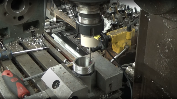
After inspecting and spending some time reverse-engineering such a unit, [Andy] then proceeded to grab some PEEK bar he had lying around and chuck it into the lathe (get it?). He notes Delrin would be more cost effective for those wishing to reproduce this, but as long as you have the ability to machine it and it’s non-conductive, there are many other options you could try.
Using no special tools other than a collet block (like this one) all the angled holes and slots were made with ease, with the help of a specially 3D-printed mount for the vise. A nice, simple approach, we think!
[Andy] tested the repeatability of the probe, mounted over his CNC-converted Holbrook lathe, reporting a value of 1 um, which seems rather good. Centering of the probe tip within the probe body was off a bit, as you’d expect for something made practically by hand, but that is less of a problem as it would seem, as it results in a fixed offset that can be compensated for in software. Perhaps the next version will have some adjustability to dial that out manually?
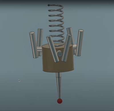
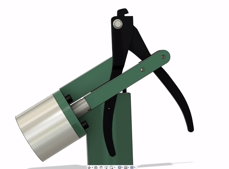
The whole assembly is formed from two plastic parts, a handful of ground-finished hardened steel pins, and a big spring. The only part remotely special is an off-the-shelf probe tip. During the electrical hookup, you may notice the use of a self-fluxing verowire pen, which was something this scribe didn’t know existed and has already placed an order for!
The reference 3D model for the design is shared from [Andy]’s Autodesk Drive for your viewing pleasure.
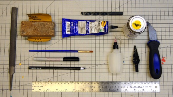
In a perfect world, we’d all have laser cutters and could pop intricate designs out of acrylic sheets with just a few clicks of the mouse. But in reality, most of us have to make do with the pedestrian tools we have at hand. For many, that might even mean everything has to be done by hand. Luckily, [Eric Strebel] has been working on a series of videos that cover how you can make professional looking parts out of acrylic using a wide array of common tools.
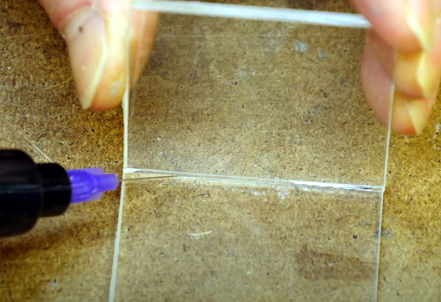
Solvent welding hand-cut pieces of acrylic.
The first video demonstrates how a simple cube can be constructed by a band saw, a table saw, and if need be, with hand tools. You might think the two power saws would have similar results, but as [Eric] explains, the table saw ends up being far more accurate and requires less post-processing to get a smooth edge. Ideally you’d run the cut pieces through a router to bevel them, but that’s a tall order for many home gamers.
As for the hand tool approach, scoring and snapping the sheets ends up making a surprisingly clean break that can actually be cleaner than the edge you’d get with a power tool. No matter how you cut them, [Eric] shows the proper way to apply the water-like solvent to your acrylic pieces to create a strong and visually attractive bond.
The next video in the series covers more advanced techniques that can still be pulled off without a top-of-the-line workshop. Sure the water-cooled acrylic bender he has is pretty slick, but if you can’t afford the $100 USD gadget, he shows you how to get similar results with an old toaster oven that you can pick up from the thrift store or even the side of the road. With some hand-made jigs and molds, you can warp and flex the heated plastic into whatever shape your project needs. Combining the tips from both videos, you might be surprised at what can be created with little more than a ruler, some hot air, and the appropriate techniques.
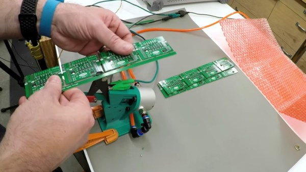
In high volume production, smaller PCBs are often “panelized” so that multiple copies can be shuffled through assembly as a single piece. Each board is attached to the panel with a few strategically placed tabs, not unlike the sprues in a plastic model kit. If you only have to separate a few boards you can simply cut them with a hand nipper, but when you’re doing hundreds or thousands of boards, it quickly becomes impractical.
Which is where [Clough42] found himself recently. Looking to improve the situation without breaking the bank, he decided to automate his trusty hand-held depanelizer tool. The basic idea was to build an actuator that could stand in for his own hand when operating the tool. He already had a pneumatic cylinder that he could power the device with, he just needed to design it.
In the video below, he walks the viewer though his CAD design process for this project. His first step, which is one that’s often overlooked by new players, is creating digital representations of the hardware he’s using. This allows him to quickly design 3D printed parts that have the proper dimensions and clearances to interface with his real-world components. Remember: it’s a lot easier to adapt your 3D model to the components on hand than the other way around.
With the appropriate valves, hoses, and a foot pedal attached to the pneumatic cylinder, he’s able to operate the cutter completely hands-free. He still has to manually move the panel around, but at least it saves him from the repetitive squeezing motion.
We’ve seen quite a few scratch built lathes here at Hackaday, but none quite like the handcrafted pole lathe put together by [Jon Townsend] and his band of Merry Men as part of their effort to build a period-accurate 18th century log cabin homestead. With the exception of a few metal spikes here and there, everything is made out of lumber harvested from the forest around them.
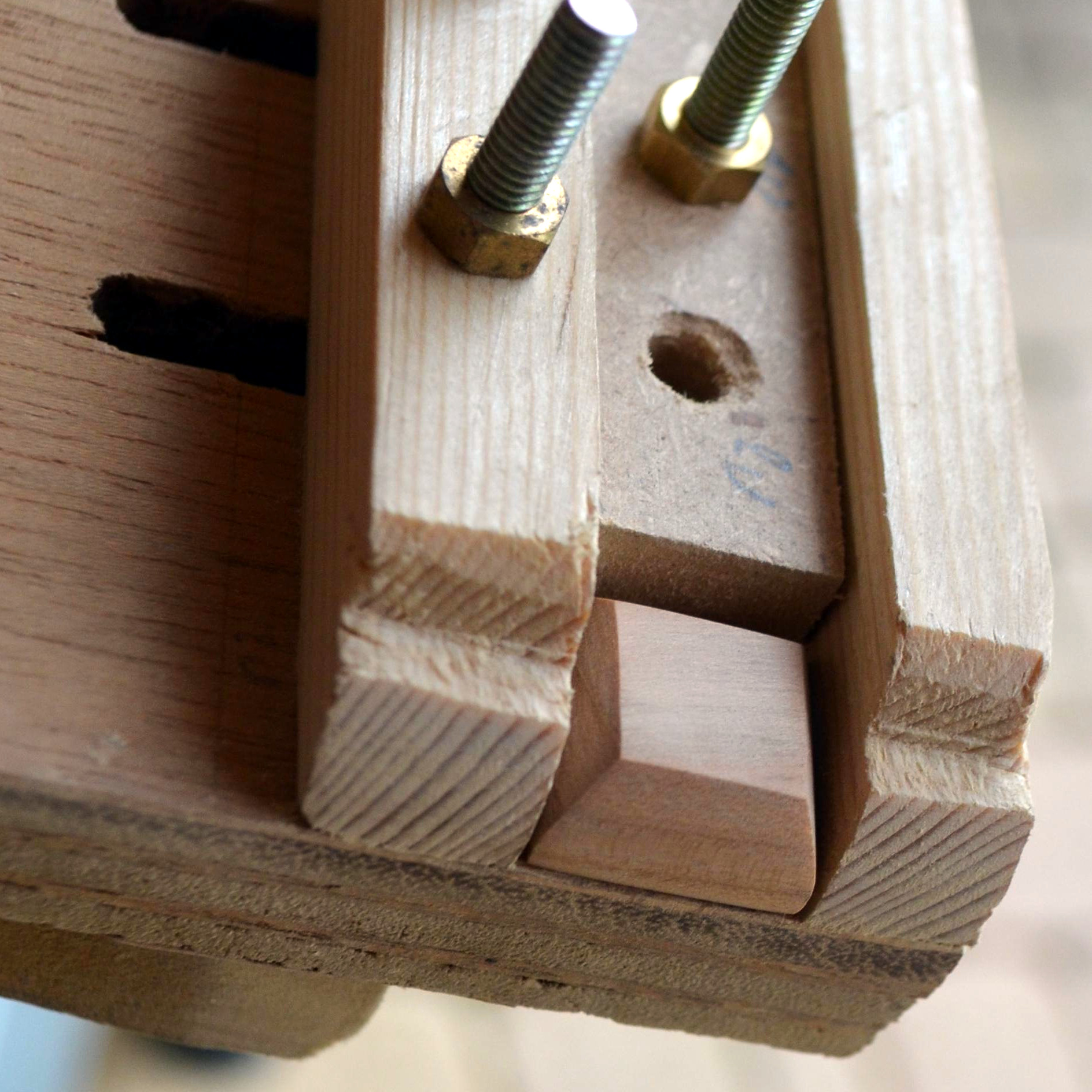
The lathe is designed to be a permanent structure on the homestead, with two poles driven into the ground to serve as legs. Two rails, made of a split log, are then mounted between them. The movable components of the lathe, known as “puppets” in the parlance of the day, are cut so they fit tightly between the rails but can still be moved back and forth depending on the size of the work piece. With two metal spikes serving as a spindle, the log to be turned down is inserted between the puppets, and wedges are used to lock everything in place.
So that’s the easy part. But how do you spin it? The operator uses a foot pedal attached to a piece of rope that’s been wound around the log and attached to a slender pole cantilevered out over the lathe. By adjusting the length and angle of this pole, the user can set the amount of force it takes to depress the pedal. When the pedal is pushed down the log will spin one way, and when the pole pulls the pedal back up, it will spin the other.
Since the tools only cut in one direction, the user has to keep letting the pressure off when the log spins back around. The fact that the work piece isn’t continuously rotating in the same direction makes this very slow going, but of course, everything was just a bit slower back in the 18th century.