Some inventions are so simple that it’s hard to improve them. The magnetic compass is a great example — a magnetized needle, a bit of cork, and a bowl of water are all you need to start navigating the globe. So why in the world would you want to over-complicate things with something like this Earth inductor compass? Just because it’s cool, of course.
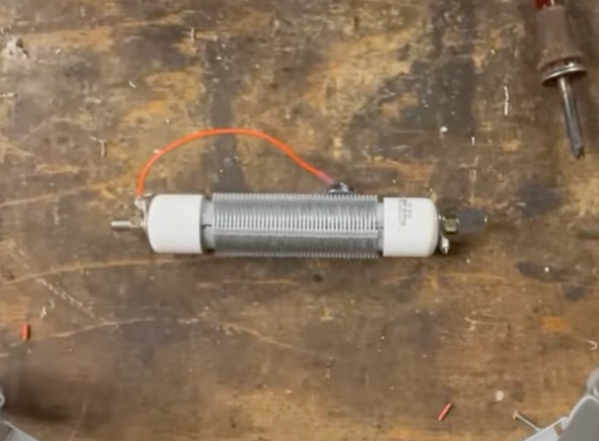
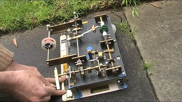
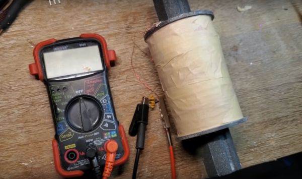
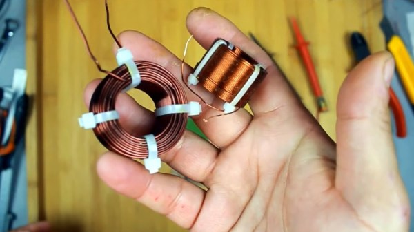
Now, the thing with complication is that it’s often instructive. The simplicity of the magnetic compass masks the theory behind its operation to some degree and completely fails to deliver any quantitative data on the Earth’s magnetic field. [tsbrownie]’s gadget is built from a pair of electric motors, one intact and one stripped of its permanent magnet stators. The two are mounted on a 3D printed frame and coupled by a long shaft made of brass, to magnetically isolate them as much as possible. The motor is powered by a DC supply while a digital ammeter is attached to the terminals on the stator.
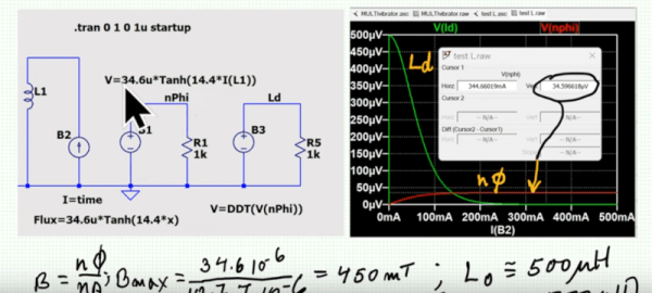
When the motor spins, the stator at the other end of the shaft cuts the Earth’s magnetic lines of force and generates a current, which is displayed on the ammeter. How much current is generated depends on how the assembly is oriented. In the video below, [tsbrownie] shows that the current nulls out when oriented along the east-west axis, and reaches a maximum along north-south. It’s not much current — about 35 microamps — but it’s enough to get a solid reading.
Is this a practical substitute for a magnetic compass? Perhaps not for most use cases, but a wind-powered version of this guided [Charles Lindbergh]’s Spirit of St. Louis across the Atlantic in 1927 with an error of only about 10 miles over the trip, so there’s that. Other aircraft compasses take different approaches to the problem of nulling out the magnetic field of the plane.
Continue reading “Overcomplicating The Magnetic Compass For A Reason”