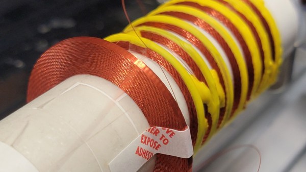
As ferrite technology has progressed into a mastery of magnetic permeability, the size of inductors has gone down to the point at which they are now fairly nondescript components. There was a time though when inductors could be beautiful creations of interleaving layers of copper wire in large air-cored inductors, achieved through clever winding techniques. It’s something that’s attracted the attention of [Brett], who’s produced a machine capable of producing something close to the originals.
Part of the write-up is an investigation of the history, these coils were once present even at the consumer level but are now the preserve of only a few highly secretive companies. They are still worth pursuing though because they can deliver the high “Q” factor that is demanded in a high quality tuned circuit. The rest of the write-up dives in detail into the design of the wire feeder, and the Arduino motor control of the project. There should be enough there for any other experimenters to try their hands at layered inductors, so perhaps we’ll see this lost art make a comeback.
Custom coils are a regular requirement for anything from radios, to musical instruments, to switching power supplies, so it’s not surprising that quite a few projects featuring them have made it here. One of the more unusual of late has been one that winds toroids.
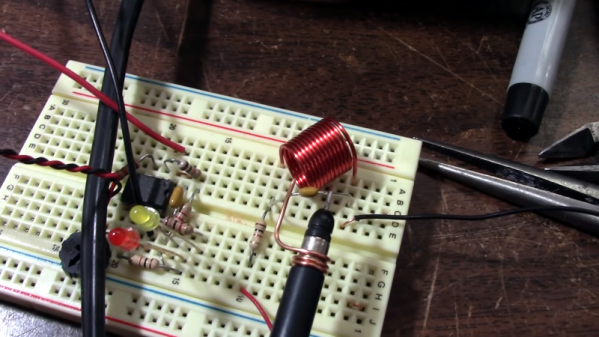
Depending on what you build, you may or may not run into a lot of inductors. If you need small value coils, it is easy to make good-looking coils, and [JohnAudioTech] shows you how. Of course, doing the winding itself isn’t that hard, but you do need to know how to estimate the number of turns you need and how to validate the coil by measurement.
[John] uses a variety of techniques to estimate and measure his coils ranging from math to using an oscilloscope. He even uses an old-fashioned nomogram from a Radio Shack databook circa 1972.
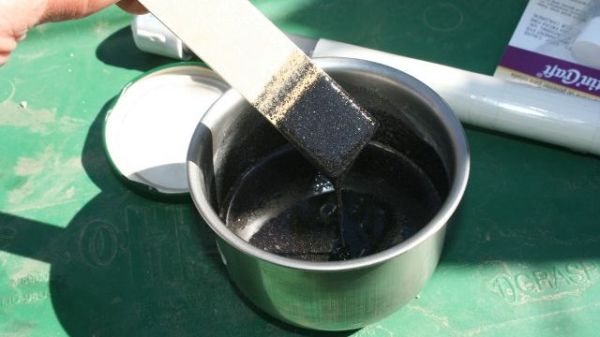
A couple months back, [macona] got his hands on a 300 watt Rofin CO2 laser in an unknown condition. Unfortunately, its condition became all too known once he took a peek inside the case of the power supply and was confronted with some very toasty components. It was clear that the Magic Smoke had been released with a considerable bit of fury, the trick now was figuring out how to put it back in.
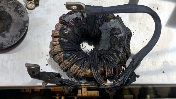
The most obvious casualty was an incinerated output inductor. His theory is that cracks in the ferrite toroid changed its magnetic properties, ultimately causing it to heat up during high frequency switching. With no active cooling, the insulation cooked off the wires and things started to really go south. Maybe. In any event, replacing it was a logical first step.
If you look closely, you may see the failed component.
Unfortunately, Rofin is out of business and replacement parts weren’t available, so [macona] had to wind it himself with a self-sourced ferrite and magnet wire. Luckily, the power supply still had one good inductor that he could compare against. After replacing the coil and a few damaged ancillary wires and connectors, it seemed like the power supply was working again. But with the laser and necessary cooling lines connected, nothing happened.
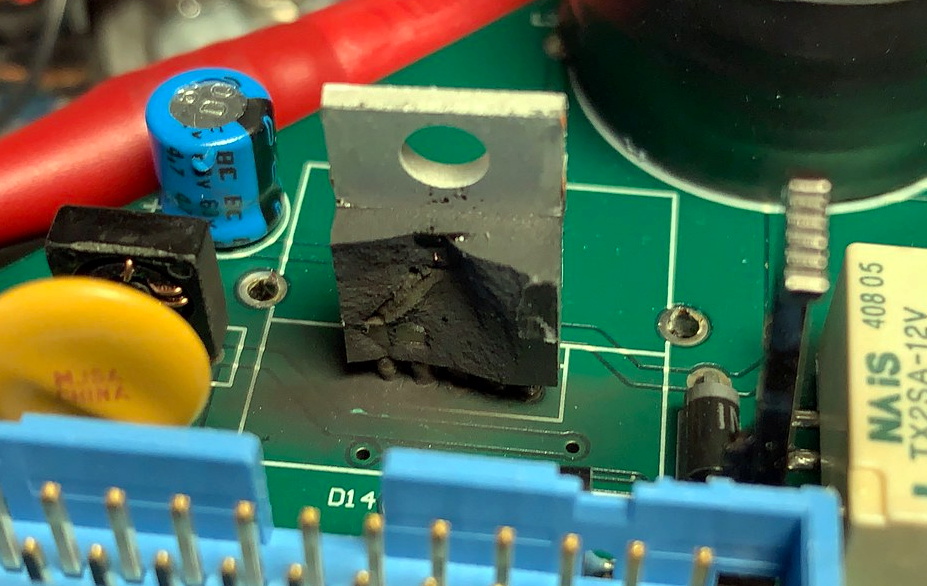
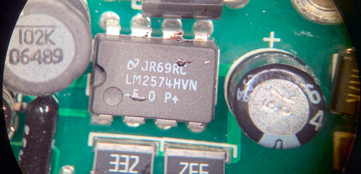
A close look at the PCB in the laser head revealed that a LM2576HVT switching regulator had exploded rather violently. Replacing it wasn’t a problem, but why did it fail to begin with? A close examination showed the output trace was shorted to ground, and further investigation uncovered a blown SMBJ13A TVS diode. Installing the new components got the startup process to proceed a bit farther, but the laser still refused to fire. Resigned to hunting for bad parts with the aid of a microscope, he was able to determine a LM2574HVN voltage regulator in the RF supply had given up the ghost. [macona] replaced it, only for it to quickly heat up and fail.
This one is slightly less obvious.
Now this was getting ridiculous. He replaced the regulator again, and this time pointed his thermal camera at the board to try and see what else was getting hot. The culprit ended up being an obsolete DS8922AM dual differential line transceiver that he had to source from an overseas seller on eBay.
After the replacement IC arrived from the other side of the planet, [macona] installed it and was finally able to punch some flaming holes with his monster laser. Surely the only thing more satisfying than burning something with a laser is burning something with a laser you spent months laboriously repairing.
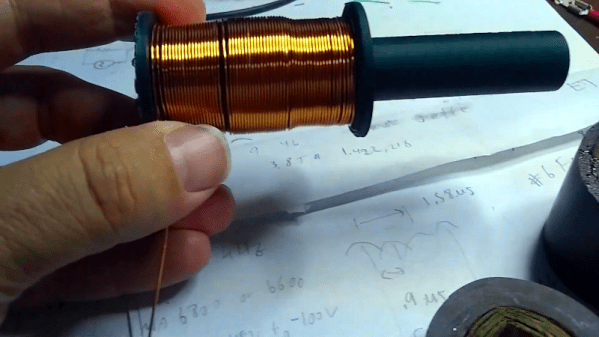
Inductors are not the most common component these days and variable ones seem even less common. However, with a ferrite rod and some 3D printing, [drjaynes] shows how to make your own variable inductor. You can see him show the device off in the video below.
The coil itself is just some wire, but the trick is moving the ferrite core in and out of the core. The first version used some very thick wire and produced an inductor that varied from 6 to 22 microhenrys. Switching to 22 gauge wire allowed more wire on the form. That pushed the value range to 2 to 12 millihenrys.
Whatever kind of clock you’re interested in building, you’re going to need to build an oscillator of some sort. Whether it be a pendulum, a balance wheel, or the atomic transitions of cesium or rubidium, something needs to go back and forth in a predictable way to form the timebase of the clock. And while it might not make the best timepiece in the world, a tuning fork certainly fits the bill and makes for a pretty interesting clock build.
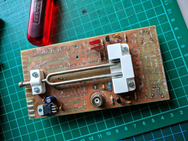
One of the nice things about this build is that [Kris Slyka] got their inspiration from a tuning fork clock that we covered a while back — we love it when someone takes a cool concept and makes it their own. While both clocks use a 440 Hz tuning fork — that’s an A above middle C for the musically inclined — [Kris] changed up the excitation method for their build. She used a pair of off-the-shelf inductors, placed near the ends of each arm and bridged by a strong neodymium magnet to both sense the 440-Hz vibrations and to provide the kick needed to keep the fork vibrating.
As for the aesthetic of the build, we think [Kris] really nailed it. Using through-hole components, old-school seven-segment displays, and a home-etched PCB, she was able to capture a retro look that really works. The RS-232 port and the bell jar enclosure complete the feel, although we’re not sure about the custom character set [Kris] designed — it’s cool and all, but makes it hard for anyone else to read without a little practice. Regardless, this is a fun build, and we’d imagine the continuous tone coming from the clock is pretty pleasing.
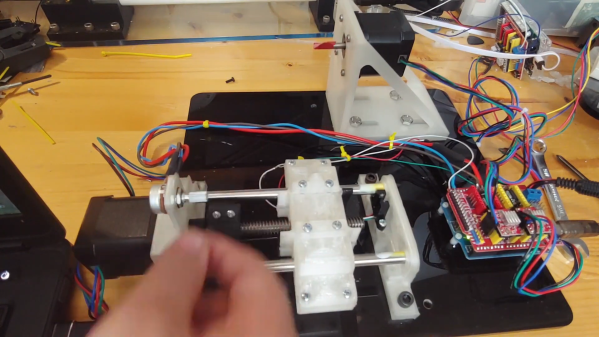
For something that’s basically a coil of wire around some magnetic pole pieces, an electric guitar pickup is a complicated bit of tech. So much about the tone of the instrument is dictated by how the pickup is wound that controlling the winding process is something best accomplished with a machine. This automatic pickup winder isn’t exactly a high-end machine, but it’s enough for the job at hand, and has some interesting possibilities for refinements.
First off, as [The Mixed Signal] points out, his pickups aren’t intended for use on a guitar. As we’ve seen before, the musical projects he has tackled are somewhat offbeat, and this single-pole pickup is destined for another unusual instrument. That’s not to say a guitar pickup couldn’t be wound on this machine, of course, as could inductors, solenoids, or Tesla coils. The running gear is built around two NEMA-17 stepper motors, one for the coil spindle and one for the winding carriage. The carriage runs on a short Acme lead screw and linear bearings, moving back and forth to wind the coil more or less evenly. An Arduino topped with a CNC shield runs the show, allowing for walk-away coil winding.
We do notice that the coil wire seems to bunch up at the ends of the coil form. We wonder if that could be cured by speeding up the carriage motor as it nears the end of the spool to spread the wire spacing out a bit. The nice thing about builds like these is the ease with which changes can be made — at the end of the day, it’s just code.
Let’s say you’re stranded on a desert island and want to get the news from the outside world. You’ll have to build your own crystal radio, of course, but your parts bin is nowhere to be found and Digi-Key isn’t delivering. So you’ll need to MacGuyver some components. Capacitors are easy with a couple of pieces of tinfoil, and a rectifier can be made from a pencil and a razor blade. But what about an inductor? Sure, air-core inductors will work, but just because you’re marooned doesn’t mean you’ve abandoned your engineering principles. Luckily, you’ve read [AC7ZL]’s treatise of making inductors from dirt, and with sand in abundance, you’re able to harvest enough material to put together some passable ferrite-core inductors.
Obviously, making your own inductive elements isn’t practical even in fanciful and contrived situations, but that doesn’t make the doing of it any less cool. The story begins with a walk in the Arizona desert many years ago, where [AC7ZL], aka [H.P. Friedrichs], spied bands of dark sand shooting through the underlying lighter sediments. These bands turned out to be magnetite, one of many iron-bearing minerals found in the area. Using a powerful magnet from an old hard drive and a plastic food container, he was able to harvest magnetite sand in abundance and refine it with multiple washing steps.
After experimentally determining the material’s permeability — about 2.3 H/m — [AC7ZL] proceeded with some practical applications. He was able to make a bar antenna for an AM radio by packing the sand into a PVC pipe and rewinding the coils around it. More permanent cores were made by mixing the sand with polyester resin and casting it into bars. Toroids were machined from fat bars of the composite on a lathe, much to the detriment of the cutting tools used.
The full-length PDF account of [AC7ZL]’s experiments makes for fascinating reading — the inductive elements he was able to create all performed great in everything from a Joule Thief to a Hartley oscillator up to 27 MHz. We love these kinds of stories, which remind us of some of the work being done by [Simplifier] and others.