The new hotness in consumer electronics might be RF remotes based on protocols like Bluetooth Low Energy, but there’s still plenty of life left in the classic infrared remote. Especially with projects like TinyRemoteXL from [Stefan Wagner], which let you build and program an IR “clicker” of your own. Whether you want to spin up your own custom universal remote or create a beefed up version of the TV-B-Gone, this open source effort is a great place to start.
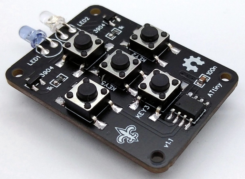
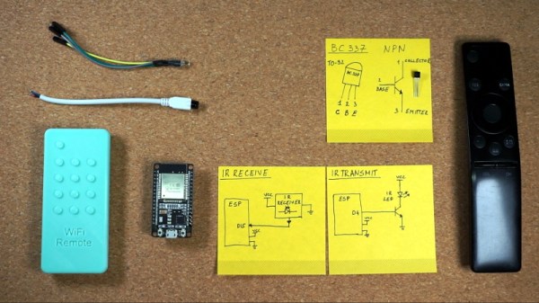
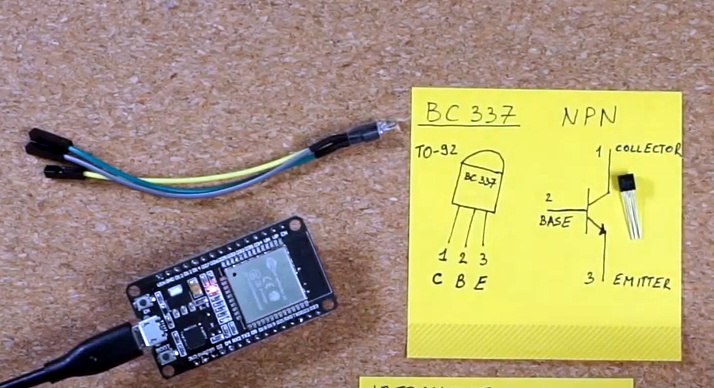
As you might have guessed from the name, this project is actually a larger version of the TinyRemote that [Stefan] put together previously. The documentation for that project goes a bit more into the nuts and bolts of talking IR, and is definitely worth a read if you’re into the low level stuff. For the original five button TinyRemote, the hardware consists of little more than a ATtiny13A microcontroller, a pair of IR LEDs, and the transistors to drive them.
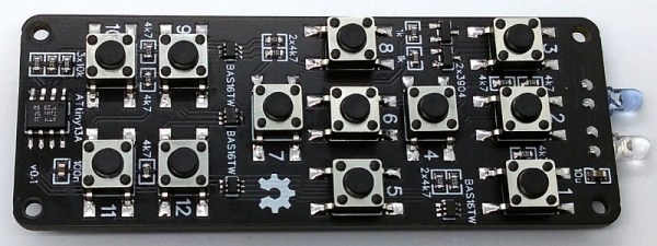
But on the XL, things are a bit trickier as there are now twelve buttons for the ATtiny13A to read. Obviously there aren’t enough pins to read so many buttons directly, but with a combination of BAS16TW diode arrays and resistors, [Stefan] is able to detect what button was pressed using the chip’s interrupt pin and ADC. Certainly a handy trick to have in the back of your mind, and the open source nature of this project gives you a great chance to see how it’s implemented.
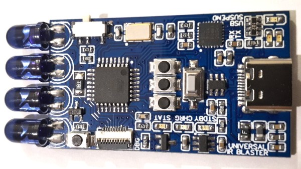
Between this project and the impressive development board [Djordje Mandic] released recently, it seems we’re looking at something of an infrared hacking revival. Earlier this year we even saw the commercial release of an IR-equipped ESP8266 board.