We covered [wk057] and his Tesla Model S battery teardown back in September. Since then we had some time to catch up with him, and ask a few questions.
You’ve mentioned that you have a (non hacked) Tesla Model S. What do you think of the car?
It’s the best car I’ve ever driven or owned, period. Not to get too into it, but, I love it. I’ve put almost 20,000 miles on it already in under a year and I have no real complaints. Software feature requests… but no complaints. After almost a year, multiple 1700-miles-in-a-weekend trips, and an overall great experience… I can never go back to a gas vehicle after this. It would be like going back to horses and buggies.
A salvage Tesla Lithium battery had to be expensive compared to a Lead Acid setup. What made you go with the Tesla?
Actually, if you consider that the Model S battery is already pre-setup as a high-capacity pack, contains the wiring to do so, and the modules are much more energy and power dense than any lead acid battery bank, it’s actually almost cheaper than a comparable lead acid bank and all the trimmings.
I haven’t officially weighed them, but the modules from the Model S battery are roughly 80 lbs. 80 lbs for a 5.3 kWh battery is around 15 lbs per kWh, which is impressive. For comparison, a decent lead acid battery will have a little over 1 kWh (of low-rate discharge capacity) and weigh almost the same.
Also, the Tesla pack is much more powerful than a lead acid bank of the same capacity.
Generally a lead acid battery bank would have a capacity that would only be realized with slow discharges, so, 1/20C. Much over that and you sacrifice capacity for power. 1/20C for an 85kWh pack is only 4.25kW, barely enough for a central air unit and some lights without losing capacity.
Now the Tesla pack can be discharged (based on how it does so in the vehicle) at up to 3.75C for short periods, and at 1/2C continuously without really affecting the overall capacity of the pack. That means I can run 10x more power than lead acid without a loss in overall charge capacity. Leads to a much more flexible battery solution since the loads will, in reality, always be so low that this will not even come into play with the Tesla pack, but would almost always be a factor with lead acid.
Charging is also somewhat better with the Tesla battery. Charge a lead acid battery at a 1/2C and it will boil. Charge the Tesla pack at 1/2C (42kW) and it might warm up a few degrees. Oh, and the charging losses at high rates are much less than lead acid also.
Overall, without continuing to yack about the technical aspects, it’s just a much better battery, takes up less space, weighs less, and has more power available.
There are likely decent arguments for other solutions, but the rest aside, this one won out because it was definitely more interesting.
Click past the break to read the rest of our interview with [wk057]!
Continue reading “An Interview With Tesla Battery Hacker [wk057]” →
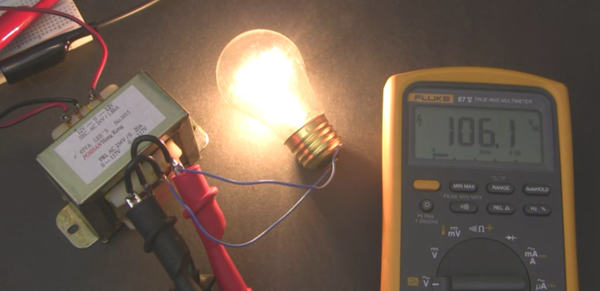
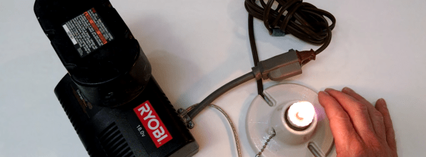
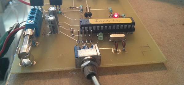
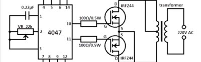 [Afroman], no stranger to these pages, has published a video in which he investigates the 4047 inverter, and draws attention to some of its shortcomings. It is not the circuit’s lack of frequency stability with voltage that worries him, but the high-frequency ringing at the point of the square-wave switching when the device has an inadequate load. This can reach nearly 600 volts peak-to-peak with a 120 volt American transformer, or over a kilovolt if you live somewhere with 230 volt mains. The Internet’s suggested refinement, a capacitor on the output, only made the situation worse. As he remarks, it’s fine for powering a lightbulb, but you wouldn’t want it near your iPhone charger.