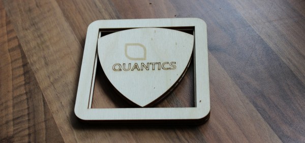
What’s better than a cool build? A cool build with valuable advice! Add a few flashy pictures and you have [Martin Raynsford]’s Reuleaux triangle coasters blog post. [Martin Raynsford] wanted to share his advice about the importance of using jigs and we’re sold. He was able to make 100 coasters in a single day and if he’s like us, after number ten, the work gets a little hurried and that is when mistakes are made.
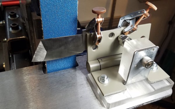
Jig is a broad term when it comes to tooling but essentially, it holds your part in place while you work on it. In this case, a jig was made to hold the coaster pieces while they were glued together. [Martin Raynsford] didn’t need any registration marks on the wood so even the back is clean. If you look closely, the coaster is two parts, the frame and the triangle. Each part is three layers and they cannot separated once the glue dries. If any part doesn’t line up properly, the whole coaster is scrap wood.
This robot arm engraved 400 coasters in a day but maybe you would prefer if you simply had your beer delivered to your new coasters.