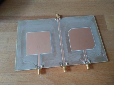
PCB inductors are a subject that has appeared here at Hackaday many times, perhaps most notably in the electromagnetic exploits of [Carl Bugeja]. But there is still much to be learned in the creation of the inductors themselves, and [atomic14] has recently been investigating their automatic creation through scripting.
A simple spiral trace is easy enough to create, but when for example creating a circular array of coils for an electric motor there’s a need for more complex shapes. Drawing a trapezoidal spiral is a surprisingly difficult task for a script, and we’re treated to a variety of algorithms in the path to achieving a usable design.
Having perfected the algorithm, how to bring it into KiCAD? The PCB CAD package has its own Python environment built-in, but it’s not the most flexible in which to develop. The solution is to write a simple JSON interpreter in KiCAD, and leave the spiral generation to an external script that passes a JSON. This also leaves the possibility of using the same code in other PCB packages.
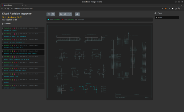
Last time, I’ve shown you how to create a local Git repository around your PCB project. That alone provides you with local backups, helping you never lose the changes you make to your files, and always be able to review the history of your project as it developed.
However, an even more significant part of Git’s usefulness is the ability to upload our creations to one of the various online Git repository hosting services, and keep it up to date at all times with a single shell command. I’d like to show you how to upload your project to GitHub and GitLab, in particular!
A team from the Institute for Automation of Complex Power System (ACS) at RWTH Aachen University have been working for a while on the analysis of widely distributed power systems. In a drive to move away from highly specialised (and expensive) electronics platforms, they have produced some instrumentation designed to operate with the Raspberry Pi platform, and an open source software stack. They call the platform the SMU (Synchronised Measurement Unit.) The SMU consists of a HAT sitting on an RPi3, inside a 3D printed box that is intended to attach to a DIN rail. After all, this is supposed to be an industrial platform.
Hardware wise, the star of the show is the Texas Instruments ADS8588S which is a 16-bit 8-channel simultaneous sampling ADC. This is quite a nice device, with 200 kSPS throughput and a per-channel programmable front end, packaged in a hacker-friendly 64-pin QFP. What makes this project interesting however, is how they solved the problem of controlling the sampled data acquisition and synchronisation.
By programming the ADC into byte-parallel mode, then using the BCM2837 Secondary Memory Interface (SMI) block together with the DMA, samples are transferred into memory with minimal CPU overhead. An onboard U-Blox Max-M8 GNSS module provides a 1PPS (top of second pulse) signal, which is combined with the ADC busy signal in a very simple manner, enabling both sample rate control as well as synchronisation between multiple units spread out in an installation. They reckon they can get synchronisation to within 180 ns of top-of-second, which for measuring relatively slow-changing power systems, should be enough. The HAT PCB was created in KiCAD and can be found in the SMU GitHub hardware section, making it easy to modify to your needs, or at least adjust the design to match the parts you can actually get your hands on.
[Neumi] over on Hackaday.IO wanted a simple-to-use way to drive stepper motors, which could be quickly deployed in a wide variety of applications yet to be determined. The solution is named Ethersweep, and is a small PCB stack that sits on the rear of the common NEMA17-format stepper motor. The only physical connectivity, beside the motor, are ethernet and a power supply via the user friendly XT30 connector. The system can be closed loop, with both an end-stop input as well as an on-board AMS AS5600 magnetic rotary encoder (which senses the rotating magnetic field on the rear side of the motor assembly – clever!) giving the necessary feedback. Leveraging the Trinamic TMC2208 stepper motor driver gives Ethersweep silky smooth and quiet motor control, which could be very important for some applications. A rear-facing OLED display shows some useful debug information as well as the all important IP address that was assigned to the unit.
Control is performed with the ubiquitous ATMega328 microcontroller, with the Arduino software stack deployed, making uploading firmware a breeze. To that end, a USB port is also provided, hooked up to the uC with the cheap CP2102 USB bridge chip as per most Arduino-like designs. The thing that makes this build a little unusual is the ethernet port. The hardware side of things is taken care of with the Wiznet W5500 ethernet chip, which implements the MAC and PHY in a single device, needing only a few passives and a magjack to operate. The chip also handles the whole TCP/IP stack internally, so only needs an external SPI interface to talk to the host device.
What would a HAL9000 look like if it eye were yellow and sat atop a front panel inspired by an Altair 8800? You’d have today’s feature, [Stephan]’s BerlinUhr, a gorgeous little take on a Berlin Clock.
At Hackaday, we have a soft spot for clock builds. They’ve graced our pages from early times. When we saw this ultra cool Berlin Clock, we couldn’t resist the urge to share it with all of our readers. For those of you not familiar with a Berlin Clock, it’s a clock that consists of 24 lights, and was the first of its kind back in 1975.
[Stephan]’s build is notable because not only is it a beautiful design, but the work that went into the design and build. At several inches tall, the BerlinUhr is supported solely by a USB-C connection, although it can also be hung on a wall. The RTC is backed up by a CR1216, and an ATtiny167 provides the brains for the operation.
A neat part of the build comes with the KPS-3227 light sensor, used to adjust the LED brightness according to ambient lighting. Rather than being a straightforward part to insert into the PCB, KiCad’s footprint had some pins reversed, causing [Stephan] to learn how to correct it and contribute the fix to KiCad. Well done!
The first PCBs we built involved a draftsman laying out large pieces of tape. The finished artwork would be photographically reduced to produce the board. This solved a few problems. It was easier to work on the large pieces and any errors were reduced by the scale amount. Boards from this era have a distinct appearance because the tracks are generally curved. But when computer-aided drafting took over, the early packages couldn’t deal with wavy lines making all sorts of angles. So traces started appearing at very common angles like 45 degrees or 90 degrees only. If you use KiCAD, though, there’s no reason to have rectilinear traces. Now there is a plugin to help make your boards appear like old-fashioned circuit boards.
The video by [mitxela] below talks about how we got here and debunks some common myths about PCB design. The plugin produces rounded corners and teardrop-shaped pads. There’s also a second post on the topic with more details. The effect isn’t just ornamental. There are some reasons graceful traces might be better than sharp angles.
Robotic mowers are becoming a common sight in some places, enabled by the cost of motors and the needed control electronics being much lower, thanks to the pace of modern engineering. But, in many cases, they still appear to be really rather dumb, little more than a jacked up bump-and-go with a spinning blade. [Clemens Elflein] has taken a cheap, dumb mower and given it a brain transplant based around a Raspberry Pi 4 paired up with a Raspberry Pi Pico for the real time control side of things. [Clemens] is calling this OpenMower, with the motivation to create an open source robot mower controller with support for GPS navigation, using RTK for extra precision.
The donor robot was a YardForce Classic 500, and after inspection of the control PCB, it looks like many other robot mower models are likely to use the same controller and thus be compatible with the openmower platform. A custom mainboard houses the Pi 4 and Pico, an ArduSimple RTK GPS module (giving a reported navigational accuracy of 1 cm,) as well as three BLDC motor drivers for the wheels and rotor. Everything is based on modules, plugging into the mainboard, reducing the complexity of the project significantly. For a cheap mower platform, the Yardforce unit has a good build quality, with connectors everywhere, making OpenMower a plug and play solution. Even the user interface on top of the mower was usable, with a custom PCB below presenting some push buttons at the appropriate positions.
Motor control is courtesy of the xESC project, which provides FOC motor control for low cost, interfacing with the host controller via a serial link. This is worth looking into in its own right! On the software side of things, [Clemens] is using ROS, which implements the low level robot control, path planning (using code taken from Slic3r) as well a kinematics constraints for object avoidance. The video below, shows how simple the machine is to operate — just drive it around the perimeter of lawn with a handheld controller, and show it where obstacles such as trees are, and then set it going. The mower is even capable of mowing multiple lawns, making the journey between them automatically!