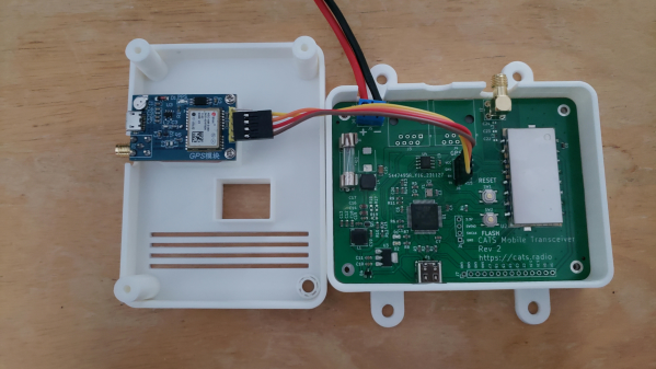
Our PCBs greatly benefit from cases – what’s with all the pins that can be accidentally shorted, connectors that stick out of the outline, and cables pulling the board into different directions. Designing a case for your PCB might feel like a fair bit of effort – but it likely isn’t, thanks to projects like turbocase from [Martijn Braam].
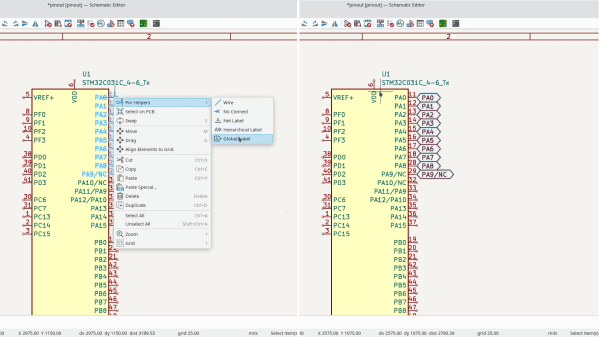
This script generates simple and elegant OpenSCAD cases for your KiCad PCBs – you only need to draw a few extra lines in the PCB Editor, that’s it. It makes connector openings, too – add a “Height” property to your connector footprints to have them be handled automatically. Oh, and there’s a few quality-of-life features – if your project has mounting holes, the script will add threaded-insert-friendly standoffs to the case; yet another argument for adding mounting holes to your boards, in case you needed more.
Installing the script is a single line, running it is merely another, and that will cover an overwhelming majority of boards out there; the code is all open too, of course. Want some more customization? Here’s some general project enclosure tutorials for OpenSCAD, and a KiCad-friendly StepUp tutorial. Oh, and of course, there’s many more ways to enclose PCBs – our own [Bob Baddeley] has written a guide to project enclosures that you are bound to learn new things from.
We thank [adistuder] for sharing this with us!