Printed Perching Pals Proliferate

Anansi in African folktale is a trickster and god of stories, usually taking physical form of a spider. Anansi’s adventures through oral tradition have adapted to the situation of people telling those stories, everything ranging from unseasonable weather to living a life in slavery. How might Anansi adapt to the twenty-first century? [odd_jayy] imagined the form of a cyborg spider, and created Asi the robot companion to perch on his shoulder. Anyone who desire their own are invited to visit Asi’s project page.

Asi was inspired by [Alex Glow]’s Archimedes, who also has a project page for anyone to build their own. According to [Alex] at Superconference 2018, she knew of several who have done so, some with their own individual customization. [odd_jayy] loved the idea of a robot companion perched on his shoulder but decided to draw from a different pool of cultural folklore for Asi. Accompanying him to various events like Sparklecon 2019, Asi is always a crowd pleaser wherever they go.

Like every project ever undertaken, there is no shortage of ideas for Asi’s future and [odd_jayy] listed some of them in an interview with [Alex]. (Video after the break.) Adding sound localization components will let Asi face whoever’s speaking nearby. Mechanical articulation for legs would allow more dynamic behaviors while perched, but if the motors are powerful enough, Asi can walk on a surface when not perched. It’s always great to see open source projects inspire even more projects, and watch them as they all evolve in skill and capability. If they all become independently mobile, we’ll need clarification when discussing the average velocity of an unladen folklore robot companion: African or European folklore?

Continue reading “Printed Perching Pals Proliferate”

Bixel, An Open Source 16×16 Interactive LED Array

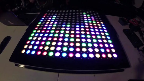
The phrase “Go big or go home” is clearly not lost on [Adam Haile] and [Dan Ternes] of Maniacal Labs. For years they’ve been thinking of creating a giant LED matrix where each “pixel” doubled as a physical push button. Now that they’ve built up experience working on other LED projects, they finally decided it was time to take the plunge and create their masterpiece: the Bixel.

Creating the Bixel (a portmanteau of button, and pixel) was no small feat. The epic build is documented in an exceptionally detailed write-up on the team’s site, in addition to the time-lapse video included after the break. [Adam] tells us the Bixel took around 100 hours of assembly, and we don’t doubt it. This is truly one of those labors of love which is unlikely to be duplicated, though all of the source files for both the hardware and software are available if you’re feeling brave enough.

The write-up contains a lot of fascinating detail about the design and construction of the Bixel, but perhaps the least surprising of all of them is that the final product ended up being very different from what they originally envisioned. The plan was to simply use lighted arcade buttons in a 16×16 grid, as they were purpose-built for exactly what the guys had in mind. But when they priced them out, the best they could do was $2 a pop. That’s $500 for just the buttons alone, before they even got into the enclosure or electronics. Like any good hackers, [Adam] and [Dan] decided to ditch the ready-made solution and come up with something of their own.

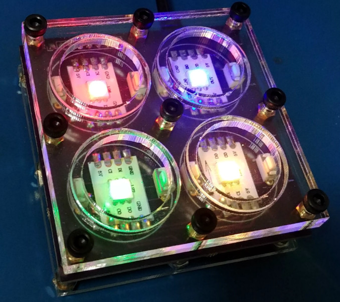
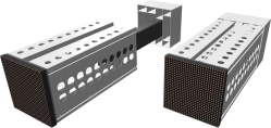
In the end, they cut the individual LEDs out of RGB strips, and soldered them down to their custom designed 500mmx500mm PCB. To the sides of each section of strip are two tactile switches, and above is a “sandwich” made of laser cut acrylic. The sheet closest to the LEDs has a 25mm hole, the top sheet has a 20mm hole, and between them is a circle of acrylic that acts as the “button”. Once it’s all screwed together, the button can’t fall out of the front or move from side to side, but it can be pushed down to contact the tactile switches.

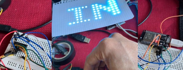
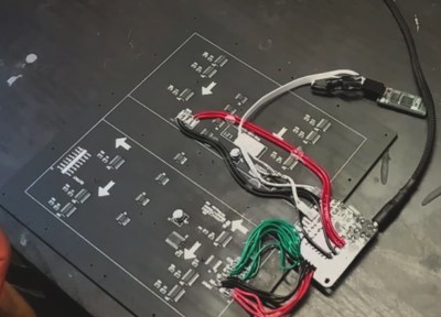
To wire it all up they took a cue from the DIY keyboard scene and used a Teensy, some 595 shift registers, and 256 1N4148 diodes. A Raspberry Pi running their Python framework does the heavy computational lifting, leaving the Teensy to just handle talking to the hardware. Overall it’s a fantastic design to emulate if you’re looking to create large arrays of buttons on the cheap; such as whenever you get around to building that starship simulator.

Continue reading “Bixel, An Open Source 16×16 Interactive LED Array”

Coca-Cola's 3D sign

Coca-Cola’s New 3D Times Square Sign Invokes Inceptionism

Coca-Cola has updated their sign in Times Square, and this one has a mesmerizing 3D aspect to it, giving the spooky feeling you get from watching buildings curl up into the sky in the movie, Inception. That 3D is created by breaking the sign up into a 68’x42′ matrix of 1760 LED screens that can be independently extended out toward the viewer and retracted again. Of course, we went hunting for implementation details.

Moving Cube Module
Moving Cube Module

On Coca-Cola’s webpage listing the partners involved in putting it together, Radius Displays is listed as responsible for sign design, fabrication, testing and installation support. Combing through their website was the first step. Sadly we found no detailed design documents or behind-the-scenes videos there. We did find one CAD drawing of a Moving Cube Module with a 28×28 matrix of LEDs. Assuming that’s accurate then overall there are 1,379,840 LEDs — try ordering that many off of eBay. EDIT: One behind-the-scenes video of the modules being tested was found and added below.

So the patent hunting came next, and that’s where we hit the jackpot. Read on to see the results and view the videos of the sign in action below.

Continue reading “Coca-Cola’s New 3D Times Square Sign Invokes Inceptionism”

LED display controlled by Bluetooth speaker

How Many Hacks In An LED Display?

There are so many nice hacks in [Joekutz]’s retro LED display project that it’s hard to know where to start. There’s his DIY LED display controlled by an Arduino UNO. To have some text or picture for the display, he’s wired the output of a Bluetooth speaker directly to the Arduino, and sends it speaker tones that encode the text to draw. And as if that wasn’t enough, he’s hacked a quartz driver board from an analog clock to use the display as a clock as well.

Let’s start with the LED matrix display, perhaps the best excuse for trying your hand at shift registers. This display uses two such 8-bit shift registers daisy chained together feeding two 8-bit Darlington arrays. The display has ten rows of sixteen columns, and you guessed it, the columns are controlled by the sixteen shift registers. Two Arduino pins tell the shift registers which column to turn on. The rows are turned on and off using ten transistors controlled by ten more Arduino pins. Scanning at 80 frames per second he gets a nice, flickerless display.

To make both the LED matrix circuit board and the control board, [Joekutz] carved out isolation paths in copper clad boards using his homemade CNC mill. Be sure to check out the first video below to see his misadventures with it that ultimately led to his gorgeous boards.

Continue reading “How Many Hacks In An LED Display?”

Graduation cap LED display demo

Stealthy Mortar Board Unleashes Bling At Graduation Ceremony

Decorating graduation caps is often frowned upon by the administration but [Dan Barkus] is challenging his school authorities to keep from smiling when they see what he has in store. His build will dazzle the audience by mounting 1024 RGB LEDs in a 32×32 matrix on top of his cap, but hidden under the cap’s black cloth. When the LEDs are off he’s indistinguishable, and when he fires up the LEDs, shine through and put on a heck of a show. He can type messages on his phone to be displayed on the cap. He can even display images and animated GIFs.

LED array control components

The LED display is an Adafruit 32×32 RGB LED matrix panel.  To control the display, [Dan] uses a Teensy, a 32 bit ARM Cortex-M4 microcontroller board. Wireless communication is done via a JBtek HC-06 Bluetooth board.

The LED display can draw up to 4 amps at full white brightness so he picked up a USB battery with two output ports, one capable of 2.1 amps and the other 2.4 amps. He then hacked together a cable that has two USB connectors on one end, connected in parallel, and a DC jack on the other end. Altogether the battery bank is capable of up to 4.5 amps output combined out those two ports, meeting the LED display’s needs. The DC jack is plugged into the Teensy and all power goes through there.

One problem [Dan] had was that the Bluetooth module was booting up before the Teensy. It didn’t see the Teensy in time, causing the Bluetooth not to work. The solution he found is shown in the 2nd video embedded below. The fix powers the Bluetooth module separately, using a current limiting resistor and a capacitor to build up the voltage, delaying just long enough for the Teensy to win.

Continue reading “Stealthy Mortar Board Unleashes Bling At Graduation Ceremony”

Massive Flexible LED Strip Display Has Too Many Pixels?

This massive LED display was assembled on a PVC banner (it can be rolled up!) measuring 2m by 1.5m, it boasts well over 6000 pixels, and as you can see from the photo — looks fantastic.

We recently published a post on How Many LEDs are Too Many, which spawned many comments showing off even more impressive displays with even higher LED counts. This is just one of them — and making it flexible as well? That’s just the icing on the cake.

To make the display flexible, [Elektric-Junkys] had a custom PVC banner printed with stripes to help them align 58 parallel strips of WS2811 LEDs on the surface.

Continue reading “Massive Flexible LED Strip Display Has Too Many Pixels?”

FPGA Ambilight Clone Packs A Ton Of Features

[Stephen] designed a standalone Ambilight clone built around an FPGA and recently added many new features to make his design even better. His original design was based around a Spartan 3-E FPGA, but his new design uses the Papilio One board with a Spartan-6 LX9 FPGA. This gives him dedicated DSP hardware and more RAM, allowing him to add more processing-intensive features.

[Steven]’s new board can drive up to 4096 LEDs total, and each LED is colored from one of 256 segmented screen areas. The output of the LEDs is smoothed over a configurable time period which makes the result a bit more pleasant. [Steven] also added color correction matrices and gamma correction tables to make up for differences in LED coloration and so the output can be fine-tuned to the color of the wall behind the TV.

Finally, [Steven] added multiple configurations which can be stored in Flash memory. The FPGA can detect letterboxes and pillarboxes in the video stream and change to a corresponding configuration automatically, so settings rarely need to be manually adjusted. He also added an extensive serial interface to configure all of the parameters and configurations in Flash. Be sure to check out the video after the break to see his setup in action.

Continue reading “FPGA Ambilight Clone Packs A Ton Of Features”