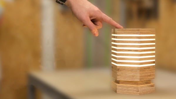
Modernizing A Soviet-era LED Matrix

Used in everything from calculators to military hardware, the 3LS363A is an interesting piece of vintage hardware. With a resolution of 5 x 7 (plus a decimal point), the Soviet-made displays contain no electronics and are simply an array of 36 green LEDs. It’s not hard to drive one of them in a pinch, but [Dmitry Grinberg] thought this classic device deserved a bit better than the minimum.

He’s developed a small board that sits behind the 3LS363A and allows you to control it over I2C for a much more modern experience when working with these vintage displays. Powered by the ATtiny406, his adapter board makes it easy to chain the modules together and even handles niceties like flipping the displayed image to account for different mounting positions. While most of us probably won’t have the chance to play around with these relatively rare displays, there’s still plenty of useful information here if you’re thinking of creating your own I2C gadgets.

In his write-up, [Dmitry] explains his rationale behind the design and some of the quirks of working with the display. For example he explains how he gave each column of the display its own FET, but to save space on the board ended up running the single decimal point (technically its own column) directly off of a spare GPIO pin. Relying on the low duty cycle, he even left current limiting resistors off the design. The end result is a tiny board that keeps the same footprint of the 3LS363A itself.

[Dmitry] went all out with developing the firmware for his new “smart” 3LS363A displays, and has written up documentation for the different commands he has implemented. From re-configuring the I2C address to updating the firmware, he’s made sure no stone was left unturned for this project. We’re not ones to shy away from a quick and dirty code, but it’s always nice to see when somebody has really put some thought into the software side of a project.

We’ve seen our fair share of oddball Soviet displays here at Hackaday, utilizing everything from heavy duty incandescent bulbs to remarkably tiny “intelligent” LEDs. While it’s unlikely any of them will dethrone the nixie as king of the retro display devices, it’s always interesting to see unusual hardware being used in the wild.

What Happened To The 100,000-Hour LED Bulbs?

Early adopters of LED lighting will remember 50,000 hour or even 100,000 hour lifetime ratings printed on the box. But during a recent trip to the hardware store the longest advertised lifetime I found was 25,000 hours. Others claimed only 7,500 or 15,000 hours. And yes, these are brand-name bulbs from Cree and GE.

So, what happened to those 100,000 hour residential LED bulbs? Were the initial estimates just over-optimistic? Was it all marketing hype? Or, did we not know enough about LED aging to predict the true useful life of a bulb?

I put these questions to the test. Join me after the break for some background on the light bulb cartel from the days of incandescent bulbs (not a joke, a cartel controlled the life of your bulbs), and for the destruction of some modern LED bulbs to see why the lifetimes are clocking in a lot lower than the original wave of LED replacements.

Continue reading “What Happened To The 100,000-Hour LED Bulbs?”

This Blinken Grid Is All Analog

The personal computers of today are economical with their employ of the humble LED. A modern laptop might have a power LED, and a hard drive indicator if you’re lucky. It was the mainframes of the ’60s and ’70s that adhered to the holy Doctrine of Blinken, flickering lamps with abandon to indicate machine activity to the skilled operators of yore. [Matseng] wanted to recreate this aesthetic, and went about it in an entirely analog fashion.

The project is built around an 8×8 LED grid, that was soldered up using a 3D printed jig for dimensional accuracy. Fitted to each column is a PNP flip flop that pulls the column to VCC, while each row has an NPN flip flop which pulls it to ground. Due to variances in component values and tolerances, the oscillators are all out of sync, leading to a remarkably pleasing blinkenlights effect.

We’re a big fan of the raw aesthetic, but [Matseng] has also fitted the grid with a diffuser which more clearly represents that vintage computer aesthetic. We’re a big fan of the blinken here, such as this loving recreation of the PDP-8/I. Video after the break. Continue reading “This Blinken Grid Is All Analog”

Samy Kamkar’s LED Balloon Network

Writing this in the frigid darkness of a Northern Hemisphere January evening, I have to admit to more than a little envy of Samy Kamkar and his friends. One of their summer events is a private party at a secluded campground somewhere that looks quite warm, which from here seems mighty attractive.

Samy wanted to provide a spectacle for his friends. What he came up with is glowing orbs; LED balloons that would float above the campsite and wow his friends with their pretty synchronised illumination. Thus an adventure in wireless communications, lighter-than-air flammable gasses versus electronics weight calculations, and code optimization began, the details of which were shared in Samy Kamkar’s 2018 Hackaday Superconference talk embedded below.

Continue reading “Samy Kamkar’s LED Balloon Network”

Building And Controlling 19 LEDs & Five Buttons From Five Outputs

Numbers are hard enough in English, but [Sadale] decided to take things a step further by building a calculator that works in Toki Pona. The result is Ilo Nanpa, an awesome hardware calculator that works in this synthetic minimal language. This is a bit harder than you might think, because Toki Pona doesn’t have digits in the same way that Neo-Latin languages like English do. Instead, you combine smaller numbers to make bigger ones. One is Wan, Two is Tu, but three is Wan Tu (1+2). As you might expect, this makes dealing and representing larger numbers somewhat complicated.

Ilo Nanpa gets around this in a wonderfully elegant way, and with some impressive behind the scenes work. The calculator has 16 LEDs, nine buttons and a slider switch, but they are all controlled and read through just five IO pins on the STM8S001J3 controller that runs the device.

That’s because {Sadale] did some remarkable work with multiplexing and charlieplexing. Multiplexing is controlling more outputs than there are control inputs by using rows and columns: it is how the LED display you are probably reading this on can be controlled by just a few wires. By switching through these rows and columns at a higher speed than the eye can see, you create the illusion of a single, continuous display.

Charlieplexing takes this a step further by using multiple voltages on a single connection to further split the signal. With the clever use of voltage dividers the directional properties of LEDs and multiple voltage levels, the Ilo Nanpa runs all of the LEDs and senses all of the buttons and the slider from just five pins. That’s a remarkably neat piece of design, and it is worth spending some time looking over the excellent explanation of the process that [Sadale] wrote to see how it is done, and poring over the code for the device to see how he programmed this all into a single low powered chip. And, while you are reading, you might pick up a few words of Toki Pona. Tawa Pona!

Continue reading “Building And Controlling 19 LEDs & Five Buttons From Five Outputs”

You’ll Never See The End Of This Project

…theoretically, anyway. When [Quinn] lucked into a bunch of 5 mm red LEDs and a tube of 74LS164 shift registers, a project sprang to mind: “The Forever Number,” a pseudo-random number generator with a period longer than the age of the universe. Of course, the components used will fail long before the sequence repeats, but who cares, this thing looks awesome!

Check out the gorgeous wire-wrapping job!

The core of the project is a 242-bit linear-feedback shift register (LFSR) constructed from (31) 74LS164’s. An XOR gate and inverter computes the next bit of the sequence by XNOR’ing two feedback bits taken from taps on the register, and this bit is then fed into bit zero. Depending on which feedback taps are chosen, the output sequence will repeat after some number of clock cycles, with special sets of feedback taps giving maximal lengths of 2N – 1, where N is the register length. We’ll just note here that 2242 is a BIG number.

The output of the LFSR is displayed on a 22×11 array of LEDs, with the resulting patterns reminiscent of retro supercomputers both real and fictional, such as the WOPR from the movie “War Games,” or the CM2 from Thinking Machines.

The clock for this massive shift register comes from – wait for it – a 555 timer. A potentiometer allows adjustment of the clock frequency from 0.5 to 20 Hz, and some extra gates from the XOR and inverter ICs serve as clock distribution buffers.

We especially love the construction on this one. Each connection is meticulously wire-wrapped point-to-point on the back of the board, a relic originally intended for an Intel SBC 80/10 system. This type of board comes with integrated DIP sockets on the front and wire-wrap pins on the back, making connections very convenient. That’s right, not a drop of solder was used on the board.

You can see 11 seconds of the pattern in the video after the break. We’re glad [Quinn] didn’t film the entire sequence, which would have taken some 22,410,541,156,499,040,202,730,815,585,272,939,064,275,544, 100,401,052,233,911,798,596 years (assuming a 5 Hz clock and using taps on bits 241 and 171 ).

Continue reading “You’ll Never See The End Of This Project”

Arduino Hunts (and Sees) The Wumpus

For anyone who’s been fiddling around with computers since the days before VGA, “Hunt the Wumpus” probably brings back fond memories. Developed in 1973, this text game has you move around a system of caves searching for the foul-smelling Wumpus, a vile creature which you must dispatch with your trusty bow and arrow. Some consider it to be one of the very first survival horror games ever developed, a predecessor to the Resident Evil franchise as well as the video game version of Hannah Montana: The Movie.

If the concept of “Hunt the Wumpus” sounds interesting to you, but you just can’t get over the whole text adventure thing, you may be in luck. [Benjamin Faure] has developed a semi-graphical version of the classic horror title which might better appeal to your 21st century tastes. Running on an Arduino Mega 2560 with graphics displayed on a 8 x 8 LED matrix, it’s not exactly DOOM; but at least you won’t have to type everything out.

You are winner!

For his handheld version of “Hunt the Wumpus”, [Benjamin] 3D printed a nice enclosure and adorned it with labels and instructions that look like tiny scrolls, a neat touch for a game that’s so old contemporary players would have called Zork a “next gen” game. While playing you can see where you’ve been and where you are currently thanks to illuminated dots on the MAX7219 display, and there are LEDs to warn you of your proximity to bottomless pits and the Wumpus itself. There’s even a piezo speaker that will chirp when a bat is nearby, which is important as they have a tendency to ruin your day by carrying you away to a random location in the cave.

Most of the game looks like an advanced version of Snake, but [Benjamin] did go through the trouble of adding some rudimentary animations and sound effects that play during specific parts of the game. When you shoot your arrow or get carried away by a bat, you’ll see a “cutscene” of sorts on the LED display. It’s a fairly simple effect, but helps break up the otherwise fairly spartan graphics and might just be enough to keep a youngins’ attention.

If you subtract a dimension, this project is reminiscent of the 1D dungeon crawler we covered last year. But if even one dimension is too many, you could always run the text version of “Hunt the Wumpus on your trusty Arduino.

Continue reading “Arduino Hunts (and Sees) The Wumpus”