We’ll take a guess that most readers have a set of digital calipers somewhere close to hand right now. The cheapest ones tend to be a little unsatisfying in the hand, a bit crusty and crunchy to use. But as [Matthias Wandel] shows us, these budget tools are quite hackable and a lot more precise than they appear to be.
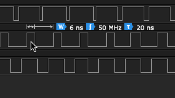
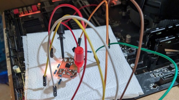
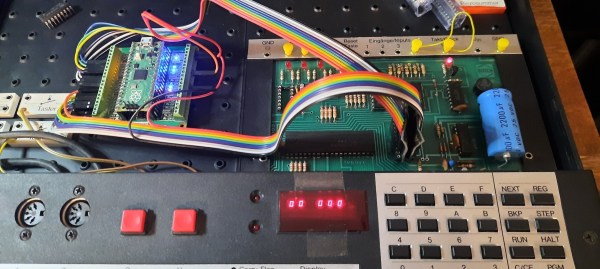
[Matthias] is perhaps best known around these parts for making machine tools using mainly wood. It’s an unconventional material for things like the CNC router he loves to hate, but he makes it work through a combination of clever engineering and a willingness to work within the limits of the machine. To assess those limits, he connected some cheap digital calipers to a Raspberry Pi by hacking the serial interface that seems to be built into all of these tools. His particular calipers output a pair of 24-bit words over a synchronous serial connection a couple of times per second, but at a level too low to be read by the Pi. He solved this with a clever resistor ladder to shift the signals to straddle the 1.8 volt transition on the Pi, and after solving some noise problems with a few strategically placed capacitors and some software debouncing, he was gathering data on his Pi.
Although his setup was fine for the measurements he needed to make, [Matthias] couldn’t help falling down the rabbit hole of trying to milk better resolution from the calipers. On paper, the 24-bit output should provide micron-ish resolution, but sadly, the readings seem to fluctuate rapidly between two levels, making it difficult to obtain an average quickly enough to be useful. Still, it’s a good exercise, and overall, these hacks should prove handy for anyone who wants to dip a toe into automated metrology on a budget.
Continue reading “Hacking Digital Calipers For Automated Measurements And Sorta-Micron Accuracy”