Turning An Analog Scope Into A Logic Analyzer

scope

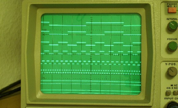
When [Marco] was planning on a storage oscilloscope build, he realized having a small device to display eight digital signals on an analog scope would be extremely useful. This just happens to be the exact description of a simple logic analyzer and managed to turn his idea into a neat little project (German, Google translation).

The theory of operation for this surprisingly simple, and something that could be completed in a few hours with a reasonably well stocked hackerspace or parts drawer in a few hours. A clock generator and binary counter are fed into the lower three bits of a simple R2R DAC, while the 8 inputs are fed into an 8-input multiplexer and sent to the last bit of the DAC. With nothing connected to the logic analyzer inputs, the output to the scope would just be an 8-step ramp that would appear as eight horizontal lines on the screen. With something connected to the logic analyzer input, an extremely primitive but still very useful logic analyzer appears on the screen.

While it’s not the greatest analyzer, it is something that can be cobbled together in an hour or two, and the capabilities are more than sufficient to debug a few simple circuits or figure out some timings in a project.

Hackaday Links: February 9, 2014

hackaday-links-chain

Here’s a quick tip to extend the usefulness of your multimeter. It’s a set of mini test hooks soldered to alligator clips with a short hunk of stranded wire in between. You can buy mini test hooks that go right on the metal probes of your meter, but the weight and bulk of the meter probes and cords sometimes get in the way. This rig allows more flexibility because of that wire.

Staying on the theme of test equipment tips, here’s a simple way to make a Y-connector for logic analyzers. [Thomas] uses a dual-row pin header, shorting each pair of pins so that both rows are connected. When this is plugged into a pin socket it leave two pins for connecting your test equipment and the rest of the project hardware.

After seeing our feature of a 3-wire Character LCD [Chad] wrote in to mention he built a 1-wire version using an ATmega328.

If you’re going to be in Anaheim this week you can stop by the ATX-West expo and see a 3D printer with a 1m x 1m x 0.5m printing area. [Thanks Martin]

Speaking of 3D printers, here’s a big delta robot (seven feet tall) outfitted for alternative material printing. It’s printing a CT scan of ribs and a heart in hot glue. This seems to be a popular material for more artistic uses. We just saw a hexapod which deposits hot glue as it roams.

The weaponized quadcopter post from Tuesday was a controversial one. The really bad part of it was the laser, which strapped to anything is extremely dangerous. But the other hack may have just been poorly executed. Hackaday alum [Jeremy Cook] wrote in to mention that fireworks and quadcopters can be used more responsibly. He strapped a sparkler to his quadro and used it to make light graffiti. You may remember that [Jeremy] wrote an introduction to light graffiti for us back in November.

Rewriting WS2812 Driver Libraries For Optimization

ws2812_compared

We like [Tim’s] drive for improvement. He wrote a WS2812 driver library that works with AVR and ARM Cortex-M0 microcontrollers, but he wasn’t satisfied with how much of the controller’s resources the library used to simply output the required timing signal for these LED modules. When he set out to build version 2.0, he dug much deeper than just optimizing his own code.

We remember [Tim] from his project reverse engineering a candle flicker LED. This time, he’s done more reverse engineering by comparing the actual timing performance of the WS2812(B) module with its published specs. He learned that although several timing aspects require precision, others can be fudged a little bit. To figure out which ones, [Tim] used an ATtiny85 as a signal-generator and monitored performance results with a Saleae logic analyzer. Of course, to even talk about these advances you need to know something about the timing scheme, so [Tim] provides a quick run-through of the protocol as part of his write-up.

Click the top link to read his findings and how he used them to write the new library, which is stored in his GitHub repository.

Hackaday Links: January 12, 2014

hackaday-links-chain

[Kyle] teaches photography and after being dismayed at the shuttering of film and darkroom programs at schools the world over decided to create a resource for film photography. There’s a lot of cool stuff on here like mixing up a batch of Rodinal developer with Tylenol, lye, and sodium sulphite, and assessing flea market film cameras. There are more tutorials coming that will include setting up a dark room, developing prints, and playing around with large format cameras.

[hifatpeople] built a binary calculator out of LEGO® bricks or toys. It started off as a series of logic gates built out of LEGO® bricks or toys in the LEGO® Digital Designer. These logic gates were combined into half adders, the half adders combined into full adders, and the full adders combined into a huge plastic calculator. Unfortunately, buying the LEGO® bricks or toys necessary to turn this digital design into a physical model would cost about $1000 using the LEGO® Pick-A-Brick service. Does anyone have a ton of LEGO® Technic® bricks or toys sitting around? We’d love to see this built.

Think you need a PID controller and fancy electronics to do reflow soldering in a toaster oven? Not so, it seems. [Sivan] is just using a meter with a thermocouple, a kitchen timer, and a little bit of patience to reflow solder very easily.

The folks at DreamSourceLabs realized a lot of electronic test equipment – from oscilloscopes and logic analyzers to protocol and RF analyzers were all included a sampling circuit. They designed the DSLogic that puts a sampler and USB plug on one board, with a whole bunch of different tools connected to a pin header. It’s a pretty cool idea for a modular approach to test equipment.

Adafruit just released an iDevice game. It’s a resistor color code game and much more educational than Candy Crush. With a $0.99 coupon for the Adafruit store, it’s effectively free if you’re buying anything at Adafruit anytime soon. Check out the video and the awesome adorable component “muppets”.

Logic Analyzers And X11

logic

[Andrew] recently scored an awesome HP 1670A Deep Memory Logic Analyzer, lucky dog. Even though this machine was built in 1992, it was a top of the line device back in the day and had a few very interesting features. This logic analyzer also had a few networking ports implementing FTP, NFS, TCP/IP, and the X11 protocols over a 10Base2 (“thinlan”) and 10BaseT (“ethertwist” seriously, that’s what’s in the manual) connections. The X11 protocol interested [Andrew] so he set this logic analyzer up so he could use it via his Linux box.

X Windows is simply a way to display GUI interfaces over a network. While today we usually only see X Windows apps confined to the desktop, in the bad old days of *NIXes you had to pay for, running a GUI app over a network was considered the wave of the future. The Internet replaced this idea with a palimpsest of JavaScript, but we digress…

[Andrew]’s new toy didn’t support DHCP, so after inputting the IP address manually, he checked the host file – still the same after twenty years – and connected with his Linux Mint box. The result is a remote control panel for the ‘ol girl in a garish color scheme that violates all modern sensibilities.

An Improvised ATtiny2313 Logic Analyzer

2313logic

After banging his head against a wall trying to get a PS/2 interface to work, [Joonas] decided he needed a dedicated logic analyzer. He didn’t need anything fancy; writing bits to a serial port would do. He came up with a very, very simple ATtiny2313-based logic analyzer that can capture at 50+ kHz, more than enough for a PS/2 port.

The hardware for [Joonas’] build is a simple ATtiny2313 breadboard adapter, an FTDI Friend, and not much else. The 2313 has eight input ports on one side of the chip, making attaching the right logic line to the right port a cinch.

The highs and lows on each logic line are sent to a computer over the FTDI chip, converted into OLS format, and piped into Open Sniffer to make some fancy graphs.

[Joonas] was able to capture PS/2 signals with his logic sniffer, so we’ll call this project a success. However, there were a few problems that made this project a little more trouble than it was worth: there is no easy way to turn a serial dump into a binary file, Putty didn’t allow suppressing output to the terminal, and Mac serial ports twinkling above 115.2 kbps don’t work natively. Still, the project did its job, and we couldn’t ask for anything more.

[via Dangerous Prototypes]

HP16500B Logic Analyzer Controlled With RS-232 And More

hp16500b-logic-analyzer

We’re pretty spoiled these days in that hobby electronics has made a lot of cool tools available on a budget. It’s hard to think of a better example than a logic analyzer, which you can get for a day or two of pay. Consumer-level devices just didn’t exist until a few years ago. [Jouko S] has this HP16500B industrial grade logic analyzer in his shop. It’s from the early 1990’s and it’s got a ton of features. Grabbing a still functional yet super-old model used to be the only way for hobbyists. But one thing you won’t find on it is the ability to connect it to your USB port to get screen captures. Younger readers might not recognize the slot at the top for magnetic media called a floppy disk which is the in-built way of recording your sessions. He set out to find an easier way to get color screen captures and ended up adding RS-232 control to the old hardware.

There is a 25-pin port on the back of the old hulk. But it is a female connector and he didn’t have the adapters on hand to make it work with his serial-to-USB converter. During development he used a breadboard and solder-tail connector to patch into the necessary signals. This was all hooked up to a Raspberry Pi which he planned to dedicate to the system. It worked, and he was able to use an interactive terminal for the rest of his sleuthing. With much trial and error he figured out the commands, and wrote some Python code for the Pi side of the equation. He can now pull color screenshots with ease thanks to the utilities available in the Python Imaging Module.