True Craftsmanship: Pneumatic Powered Drone Wasn’t Made To Fly

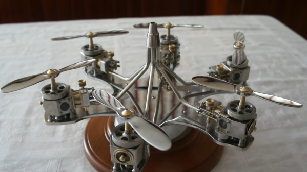
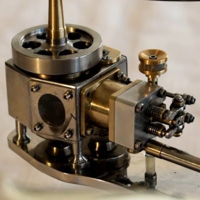
From time to time it’s good to be reminded that mechanical engineering can also be art. [José Manuel Hermo Barreiro], also known as [Patelo], is a retired naval mechanic with a love for scale model engines. Using only basic tools and a lathe, he has built a non-flying hexacopter display model, each propeller turned by a tiny single cylinder motor that runs on compressed air. From the tiny components of the valve systems, the brass framed acrylic windows into the crankcases, and the persistence of vision disc on the exhaust, the attention to detail is breathtaking.

One of the six hand crafted pneumatic motors

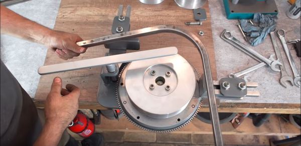
[Patelo] started the project on paper, and created a set of detailed hand-drawn blueprints to work from. Sadly a large part of the build took place during lockdown, and was not filmed, but we still get to see some work on a crankcase, connecting rod, camshaft, propellers, flywheel, and exhaust tubes. It is very clear that [Patelo] knows his way around his lathe very well, and is very creative with custom tools and jigs. The beautiful machine took approximately 1,560 hours to build, consists of 265 individually made parts held together with 362 screws.

We previously featured tiny V-12 engine that [Patelo] built around 2012. At that time he was 72 years of age, which means he should be around 80 now. We can only hope to come to emulate him one day, and that we get to see more of what comes out of his workshop. Hats off to you, sir.

Forming Sheet Metal Parts With 3D Printed Dies

Using 3D printed forms to bend sheet metal isn’t exactly new. We’ve seen several people create custom dies for their brakes, and the results have shown the concept has merit for small-scale production. But that’s usually where the process ends. A bend here or there is one thing, but the ability to form a complex shape with them has always seemed like asking too much. But judging by his recent experiments, [Shane Wighton] is very close to changing that perception.

The process at work here is, relatively speaking, pretty simple. You print out the upper and lower die, put a piece of sheet metal between them, and then smash them together with a hydraulic press. If everything works correctly, and your CAD skills hold true, the metal will take the desired shape.

Of course, that’s vastly oversimplifying things. As [Shane] explains in the video after the break, there are many nuances to forming sheet metal like this that need to be taken into account, and iteration and experimentation are basically unavoidable. So it’s a good thing you can rapidly redesign and reprint the dies.

Which isn’t to say that the dies themselves didn’t come with their own unique set of challenges. The first ones shattered under the pressure, and it took a few design revisions and eventually a switch to a stronger resin before [Shane] got a set of dies that could form the desired piece. Even still, he’s had a lot of trouble getting the printed parts to survive multiple uses. But he’s confident with some more refinements he could get a repeatable process going, and thinks ultimately producing runs of up to 100 parts on a set of printed dies isn’t out of the question.

Logically, it would seem plastic isn’t an ideal choice for punching and shaping metal. Frankly, it’s not. But if you’re doing in-house manufacturing, the ability to produce complex tooling quickly and easily can help make up for any downsides it might have.

Continue reading “Forming Sheet Metal Parts With 3D Printed Dies”

A Honeycomb Patching Robot Powered By Arduino

No, it’s not the kind of honeycomb you’re probably thinking of. We’re talking about the lightweight panels commonly used in aerospace applications. Apparently they’re rather prone to dents and other damage during handling, so Boeing teamed up with students from the California State University to come up with a way to automate the time-consuming repair process.

The resulting machine, which you can see in action after the break, is a phenomenal piece of engineering. But more than that, it’s an impressive use of off-the-shelf components. The only thing more fascinating than seeing this robotic machine perform its artful repairs is counting how many of its core components you’ve got laying around the shop.

Built from aluminum extrusion, powered by an Arduino Due, and spinning a Dewalt cut-off tool that looks like it was just picked it up from Home Depot, you could easily source most of the hardware yourself. Assuming you needed to automatically repair aerospace-grade honeycomb panels, anyway.

At the heart of this project is a rotating “turret” that holds all the tools required for the repair. After the turret is homed and the condition of all the cutting tools is verified, a hole is drilled into the top of the damaged cell. A small tool is then carefully angled into the hole (a little trick that is mechanical poetry in motion) to deburr the hole, and a vacuum is used to suck out any of the filings created by the previous operations. Finally a nozzle is moved into position and the void is filled with expanding foam.

Boeing says it takes up to four hours for a human to perform this same repair. Frankly, that seems a little crazy to us. But then again if we were the ones tasked with repairing a structural panel for a communications satellite or aircraft worth hundreds of millions of dollars, we’d probably take our time too. The video is obviously sped up so it’s hard to say exactly how long this automated process takes, but it doesn’t seem like it could be much more than a few minutes from start to finish.

Continue reading “A Honeycomb Patching Robot Powered By Arduino”

Motorizing A Plasma Cutter On The Cheap

A hand-held plasma cutter is an excellent tool to have if you are working with sheet metal, but it’s not particularly well suited to making long or repetitive cuts. Which is why [workshop from scratch] worked his usual scrapheap magic and built his own motorized track for making perfectly straight cuts.

Most of the frame, and even the small truck that rides on it, is made out of square stock in various sizes. A couple of bearings are enough to make sure the movement is smooth and doesn’t have too much slop. Motion is provided by a long threaded rod and two nuts, which are welded to the side of the truck.

If you had the patience (and forearm strength) you could just put a crank on the rod and be done with it, but in this case [workshop from scratch] used the motor, gearbox, and chuck from an old electric drill to grab onto the threaded rod and do the spinning for him. He rigged up an enclosure for the side of the rack that holds the motor, DC power supply, and motor controller, along with a couple of switches and a knob to control the speed.

A modification allows him to enable the plasma cutter with one of the switches on the panel, which gives the setup a much more complete feel than just putting a zip tie on the trigger. With this design, the plasma cutter itself can still be removed from the mount and used normally. You can even remove the motorized component with a few bolts if you just wanted to do manual cuts on the bed.

In the video after the break, the keen-eyed viewer may notice a few familiar pieces of gear in the background, such as the hydraulic bench vise we covered earlier in the year. As the name of the channel implies, [workshop from scratch] is all about building the workshop tools that many take for granted, and they’ve all been phenomenally fascinating projects. While we admire the gumption it takes to try and build a lathe out of scrap granite slabs, there’s something to be said for DIY tools that end up looking nearly as good as commercial offerings.

Continue reading “Motorizing A Plasma Cutter On The Cheap”

Build Your Own Tools For More Power

Building something on your own usually carries with it certain benefits, such as being in full control over what it is you are building and what it will accomplish, as well as a sense of pride when you create something that finally works just the way you want it. If you continue down that path, you may eventually start making your own tools to help build your other creations, and if you also have some CAD software you can make some very high quality tools like this belt grinder.

This build comes to us from [Emiel] aka [The Practical Engineer] who is known for his high quality solenoid engines. His metal work is above and beyond, and one thing he needed was a belt grinder. He decided to make a 3D model of one in CAD and then build it from scratch. The build video goes through his design process in Fusion 360 and then the actual build of this beast of a machine. The motor is 3.5 horsepower which, when paired with a variable frequency drive, can provide all of his belt grinding needs.

[Emiel]’s videos are always high quality, and his design process is easy to follow as well. We’re always envious of his shop as well, and it reminds us a lot of [Eric Strebel] and his famous designs.

Continue reading “Build Your Own Tools For More Power”

Making Your Own Chain Sprockets, The Tidy Way

Chain sprockets are a key drivetrain component in a lot of builds. Unfortunately they can be difficult to source, particularly for those outside the reach of retailers like McMaster-Carr. In such situations, you might consider making your own.

The toothed profile on a chain sprocket can be produced in a simple manner by drawing a base circle, along with a series of circles spaced appropriately for the chain in question. This involves measuring the pitch and roller diameter of the chain. With these measurements in hand, a template can be created to produce the sprocket.

From there a series of holes are drilled to rough out the basic shape of the teeth, before the sprocket is then cut down to its appropriate outer diameter. The finishing work consists of chamfering the sprocket’s thickness, as well as the filing the sharp edges of the teeth for smooth engagement.

It’s a quick and easy method for producing sprockets with well-defined, accurate profiles. We’ve featured other rough and ready methods before, too. Video after the break.

Continue reading “Making Your Own Chain Sprockets, The Tidy Way”

Bend Some Bars With A Flywheel

The ability to look at a pile of trash, and see the for treasure is a skill we hold in high regard around here. [Meanwhile in the Garage] apparently has this skill in spades and built himself a metal bar bending machine using an old flywheel and starter pinion gear.

To bend metal using muscle power alone requires some sort of mechanical advantage. Usually this involves a bending tool with a long lever, but [Meanwhile in the Garage] decided to make use of the large gear ratio between a car’s starter motor and the flywheel it drives. This does away with the need for a long lever and allows bending to almost 270° with a larger radius. Lathe and milling work features quite prominently, including to make the bend formers, drive shaft and bushings and to modify the flywheel to include a clamp. The belt sander that is used to finish a number of the parts is also his creation. While the machine tools definitely helped, a large amount of creativity and thinking outside the box made this project possible and worth the watch.

We’ve featured a number of scrap-built tools including a milling machine, sheet metal hole punch and a hydraulic bench vice. Keep them coming!